
Welcome back. In our last session, we constructed the digital "skeleton" for our automotive grab handle using a multi-body modeling strategy in CATIA logic. We defined the main body and created separate bodies for the screw boss and snap-fit features. Now that we have the fundamental structure, we must refine it to ensure it can be manufactured efficiently and without defects.
This lesson focuses on applying the "golden rules" of injection molding design. We will move beyond just creating geometry and start thinking like a manufacturing engineer. You will learn how to apply appropriate and industry-standard values for wall thickness, draft angles, and fillet radii to our grab handle model. Mastering these principles is a non-negotiable step in transforming a CAD model into a high-quality, production-ready part.
The Three Pillars of Injection Molding DFM
For any injection-molded part, three core geometric considerations dictate its manufacturability, cost, and in-service performance. We will examine each one and apply it to our grab handle design.
1. Wall Thickness
Consistent wall thickness is arguably the most important rule in plastic part design. Variations in thickness cause the plastic to cool and shrink at different rates, leading to critical defects.
- Too Thick: Sections that are too thick take longer to cool, increasing cycle time and cost. They are also prone to sink marks (surface depressions) and voids (internal bubbles) as the material shrinks.
- Too Thin: Sections that are too thin may prevent the molten plastic from filling the mold completely, resulting in a short shot. They can also lead to warpage.
To get a clear overview of these principles, please watch the following short video clips.
Design Tips for Injection Moulding
Watch the section on wall thickness in the "Injection Moulding Design Guide" from Xometry Europe. It provides a concise explanation of the risks and offers a key guideline for transitions.
Focus on the discussion about the causes of sink marks and warpage, and note the rule for how to transition between different thicknesses: Wall Thickness.
In the automotive interior trim world, a nominal wall thickness of 2.0 mm to 3.0 mm is standard for parts like our grab handle. We established a nominal thickness of 2.5 mm for our PC/ABS material, which falls perfectly within this range.
The real challenge is managing thickness where we add features. As we saw in the previous lesson, simply adding a solid boss to our main wall would create a massive thick section. The correct approach is to maintain uniform thickness throughout.

Application to the Grab Handle:
- Main Body: We maintain a consistent 2.5 mm thickness by offsetting the A-surface.
- Screw Boss & Ribs: To avoid sink marks on the visible A-surface, the walls of the screw boss and any supporting ribs must be thinner than the main wall. A standard automotive rule is that rib thickness should be 40-60% of the nominal wall thickness.
- For our 2.5 mm wall, the ribs and boss walls should be approximately .
The video below reinforces this critical rib-to-wall ratio.
Injection Molding Design Tips - 10 DFM Guidelines
Watch this segment from RAPID DIRECT's "Injection Molding Design Tips" video. It specifically addresses the design of ribs and their thickness ratio.
Pay close attention to the 60% rule and the visual explanation of how it prevents sink marks: Ribs and Gussets.
2. Draft Angles
Once the part is molded, it must be ejected from the steel mold. Vertical walls will scrape against the mold surface during ejection, causing cosmetic scratches and high stress on the ejector system. To prevent this, we apply a small angle, or draft, to all walls parallel to the direction of mold opening (the "pull direction").
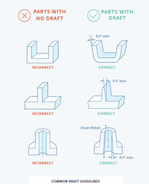
The amount of draft depends on the surface finish and depth of the feature.
[PDF] Computer-Aided Design and Manufacturability Analysis of an ...
This research paper excerpt provides automotive-specific guidelines for draft angles, distinguishing between aesthetic and structural surfaces.
Find the section titled "Manufacturability and Design-for-Assembly (DFA)". Read the paragraph on "Draft". Focus on the different requirements for Class-A (exterior/visible) faces versus interior structural faces.
As the paper highlights, the rules are clear and strict in an automotive context:
- Textured Class-A Surfaces: Require ≥ 3° of draft. The texture on the mold core would otherwise get damaged or scuff the part.
- Non-Visible Structural Faces (B-Side): Can be optimized to 1-2°.
- Polished or "Smooth" Surfaces: A minimum of 0.5-1° is often acceptable.
Application to the Grab Handle:
- Main Body: The visible, textured A-surface where the user's hand rests must have at least 3° of draft relative to the tooling axis. The B-side walls can have 1-2°.
- Screw Boss: The inner and outer cylindrical walls of the boss need draft. A standard 1° is typical.
- Snap-Fit: The vertical walls of the cantilever arm must also be drafted, typically 1-2°.
Applying draft is a fundamental step in your CATIA workflow. It should be done after creating the primary solid forms but before applying fillets.
3. Fillet & Corner Radii
Sharp internal corners are stress concentrators. When molten plastic flows into a sharp corner, it can create turbulence and weld lines. After cooling, that sharp corner becomes a weak point where cracks can initiate under load. Sharp external corners are also difficult and costly to machine into the mold tool. For these reasons, all corners should be filleted.
Design Tips for Injection Moulding
Return to the Xometry video to watch the section on fillets. It explains the core benefits and provides the fundamental rules for sizing them.
Watch from the fillets section. Internalize the relationship between internal radius, external radius, and wall thickness.
The rules of thumb for filleting are directly tied to your nominal wall thickness (T):
- Internal Radius: Should be at least 0.5 x T. For our 2.5 mm wall, this means a minimum internal radius of 1.25 mm.
- External Radius: Should be the Internal Radius + T. For our part, this would be .
Following this rule helps maintain a more consistent wall thickness as the part turns a corner, preventing a thick section from forming.
Mastering Plastic Part Design: Key Principles & Tips - ptsmake
This article from PTSMAKE offers a detailed guide on corner radii, including a helpful table and discussion of common mistakes.
Read the sections "Understanding the Importance of Corner Radii" and "Recommended Minimum Radius Guidelines". The table provides excellent quick-reference values for various wall thicknesses. Also, review the "Common Design Mistakes to Avoid" to understand the consequences of ignoring these rules.
Application to the Grab Handle:
- Feature Junctions: The transition where the screw boss and snap-fit bodies are added to the main body must have generous fillets following the T/2 rule.
- Rib Bases: The base of any reinforcing rib must be filleted to distribute load into the main wall.
- Snap-Fit Root: The base of the cantilever snap-fit arm is a high-stress area. A proper root radius is critical to its function and longevity.
Your Turn: Challenge Question
Imagine you have just used a Boolean Add operation in CATIA to join the Screw_Boss_Body to the Main_Body. This has created a sharp internal corner at the base of the boss on the B-side and a sharp external corner. Our nominal wall thickness (T) is 2.5 mm.
Based on the design rules we've just discussed:
- What is the minimum radius you should apply to the internal fillet?
- What is the corresponding radius you should apply to the external fillet?
Provide the values and briefly justify your answer.
Conclusion
In this lesson, we have elevated our grab handle from a simple geometric shape to a manufacturable design by applying the three golden rules of injection molding. These principles are not suggestions; they are fundamental requirements for producing sound, cost-effective plastic parts.
Key Takeaways:
- Uniform Wall Thickness: Aim for a consistent thickness (e.g., 2.5 mm for our part). Where features are added, their walls should be 40-60% of the nominal thickness to prevent sink marks.
- Draft Angles: All surfaces parallel to the mold pull direction must be drafted. Use ≥ 3° for textured Class-A surfaces and 1-2° for internal, structural B-side features.
- Fillet Radii: Avoid sharp corners to reduce stress and improve mold flow. A common rule is Internal Radius ≥ 0.5 x T and External Radius = Internal Radius + T.
- Modeling Sequence: The correct CATIA workflow is to model base solids, apply
Draft, performBoolean Operations, and then applyEdge Filletsas a final step.
With these rules applied, our grab handle is now far more robust. In the next lesson, we will formalize this review process by conducting a DFM (Design for Manufacturability) analysis and then a DFMEA (Design Failure Mode and Effects Analysis) to systematically identify and mitigate risks before a single piece of steel is cut for the mold.
Can't find a good explanation? Sign up and we'll make it for you
Sign up