
In our previous lesson, we established the "why" behind our design by justifying the selection of a PC/ABS blend for a single-piece grab handle. We weighed its manufacturing simplicity and balanced performance against the trade-offs of cost and strength compared to a multi-part solution. Today, we shift our focus from the why to the how.
This lesson will guide you through developing a robust modeling sequence for the grab handle. We'll translate our design requirements into solid geometry, focusing on the CATIA V5/V6 logic for creating a complex plastic part. You are familiar with the CATIA environment, so we will speak in terms of its core methodologies, which are applicable to any high-end parametric CAD system. Our primary goal is to structure the model to incorporate two critical B-side features: a screw boss for mounting and a cantilever snap-fit for assembly, ensuring the design is both functional and manufacturable.

Core Strategy: Multi-Body Modeling
For a part with multiple, distinct functional features like a grab handle, a single, linear history tree is inefficient and unstable. Instead, we will employ a multi-body modeling approach. This is a cornerstone of advanced design in CATIA.
The logic is as follows:
- Create the main body of the part.
- Create each significant feature (screw boss, snap-fit, ribs) in its own separate
Body. - Use
Boolean Operations(Add,Remove,Intersect) to assemble these bodies into the final part.
This methodology keeps the design organized, makes features independent and easier to modify, and simplifies troubleshooting.
[PDF] Definition of CAD standard that improves and enhances data ...
To reinforce this concept, review the provided excerpts from a CAD standards document.
First, read the short section on "PartBody" which contrasts single-body and multi-body modeling. You'll find it by searching for "Solid modelling can be defined as single body". Then, look for the section "Create functional areas bodies", which reinforces that multi-body modeling with Boolean operations is suitable for complex plastic parts.
Step 1: Establishing the Main Body
The foundation of our grab handle is its main form, defined by the A-surface (styling) and B-surface (engineering).
- A-Surface: We assume the
A-Surfaceis provided by the design studio. In a real project, this would be an imported surface model in yourGeometrical Setthat is considered sacred—you build from it, but you don't change it without formal approval. - B-Surface & Solid Body:
- In the
Generative Shape Design(GSD) workbench, you would analyze the A-surface for manufacturability (e.g., minimum radii for offsetting). - You would then create a new
PartBody, let's call itMain_Body. - The simplest way to create the solid is using the
ThickSurfacefeature from thePart Designworkbench, offsetting the A-surface inward to create a solid with a nominal wall thickness (e.g., 2.5 mm for PC/ABS). This automatically generates the B-surface.
- In the
With the Main_Body established, we can now build our engineering features.
Step 2: Modeling the Screw Boss
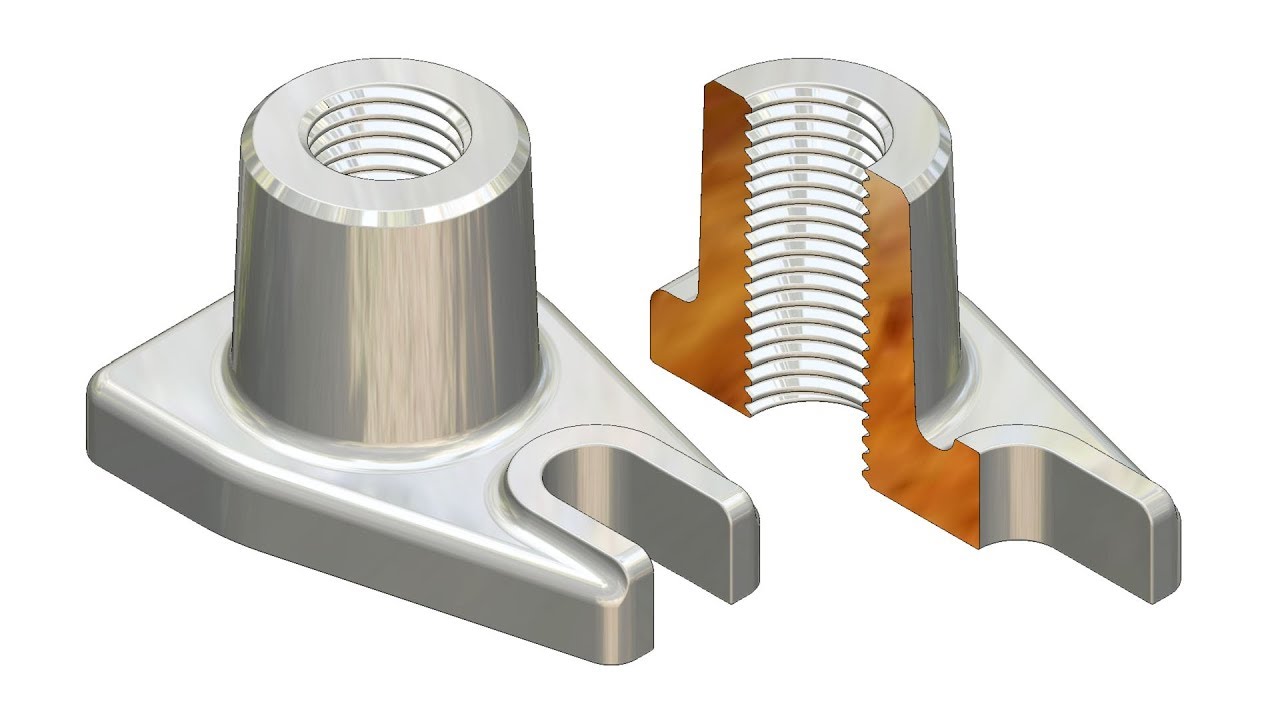
The screw boss is a critical mounting feature. Its design must balance strength, moldability, and aesthetics, specifically avoiding sink marks on the A-surface. We'll model this in a new PartBody named Screw_Boss_Body.
The following video provides an excellent, in-depth guide to creating a fully parametric and manufacturable screw boss in CATIA. We will walk through its key stages.
CATIA V5 : Design a plastic attachment feature : Screw Boss #automotive #catiav5 #3dexperience
Watch the specified sections of the video "CATIA V5 : Design a plastic attachment feature : Screw Boss" by 3D CAD Academy. It demonstrates the robust, parameter-driven methodology we are aiming for.
First, watch the introduction to understand the core design considerations: Key Considerations. Next, observe the setup of the parametric skeleton. Focus on why he creates reference points, lines, and planes before any solid geometry. This is fundamental to a flexible model: Parametric Setup. Watch the creation of the main cylinder. Note the use of formulas in the sketch for inner/outer diameters and the application of draft, which is essential for DFM: Boss Creation. Finally, and most importantly, watch the section explaining sink marks and the "doghouse" design solution. This is a critical technique for managing wall thickness in plastic part design: Sink Marks & Doghouse.
Modeling Logic Summary (CATIA V5/V6):
- Create a New Body:
Insert -> Body. Name itScrew_Boss_Body. - Define a Skeleton: In a
Geometrical Set, create a point for the boss's center and a line for its axis (tooling direction). This allows you to easily reposition the boss later without breaking the model. - Sketch the Profile: Create a
Positioned Sketchon a plane normal to the boss axis. The sketch should contain two concentric circles for the inner and outer diameters. Constrain these to the skeleton point. Use formulas to link the outer diameter to the screw size (e.g., OD = 1.5 * Screw Diameter). - Create the Boss Cylinder: Use the
Padfeature, extending the sketch up to a plane or surface that defines the boss height. In thePaddefinition, apply aDraftangle (e.g., 0.5-1.0 degrees) to the inner and outer faces for mold release. - Add Stiffening Ribs: Model ribs in a separate
Body(Rib_Body). Sketch lines radiating from the boss center, use aThin Padfeature with draft, and thenCircular Patternthem.AddthisRib_Bodyto theScrew_Boss_Body. - Design the Doghouse (if needed): To prevent sink marks where the boss meets the main wall, you would model a "doghouse" feature. This involves creating a pocket on the main body and building the boss up from the floor of that pocket, maintaining a consistent wall thickness. The video demonstrates this complex but vital technique using a multi-body approach with shells and Boolean operations.
Step 3: Modeling the Cantilever Snap-Fit
Snap-fits are an economical way to join plastic parts. We'll add a simple cantilever hook to our grab handle, which could be used to attach a trim cover. We will create this in a new Body called Snap_Fit_Body.
First, let's understand the design principles.
[PDF] Snap-Fit Joints for Plastics - A Design Guide - Covestro
This guide from Covestro is an industry-standard resource for designing snap-fits.
Read the section "A Snap Joints/General" to understand the basic types. Then, study the "Design Hints" in section "B Cantilever Snap Joints". Pay close attention to Figure 9 and the text regarding the root radius (R/h) and the benefits of tapering the snap-fit arm.
The key takeaways from the design guide are:
- The cross-section of the snap-fit arm should be tapered to distribute stress evenly.
- A generous radius at the root of the arm is critical to reduce stress concentration, but it must be balanced to avoid creating a thick section that can cause sink marks.
Modeling Logic Summary (CATIA V5/V6):
- Create a New Body:
Insert -> Body. Name itSnap_Fit_Body. - Positioned Sketch: Create a
Positioned Sketchon a plane where the snap-fit will be located. The sketch should define the 2D profile of the cantilever arm and hook. - Pad the Profile: Use the
Padcommand to extrude the sketch, creating the main form of the snap-fit. - Apply Draft: Use the
Draftcommand to apply an appropriate angle to all faces parallel to the tooling direction. This is non-negotiable for mold release. - Add Fillets: Use the
Edge Filletcommand to add the critical radius at the root of the snap arm. Add smaller fillets to other sharp edges to improve strength and mold flow.
Step 4: Final Assembly with Boolean Operations
Now that our Main_Body, Screw_Boss_Body, and Snap_Fit_Body exist independently, we will assemble them into the final PartBody.
- Define the Final Body: Select the primary
PartBody(which should contain theMain_Bodysolid). - Add Features: Use the
AddBoolean operation (found in theBoolean Operationstoolbar) to merge theScrew_Boss_Bodyinto thePartBody. - Repeat: Use the
Addoperation again to merge theSnap_Fit_Bodyinto thePartBody. - Final Fillets: After all bodies are assembled, apply final
Edge Filletsto the intersection edges between the main body and the added features. Following the sequence of Draft -> Boolean -> Fillet is a robust modeling practice.
This structured, multi-body approach results in a final part that is robust, easy to edit, and clearly communicates the design intent, separating styling from engineering features in the specification tree.
Conclusion
In this lesson, we have laid out the professional methodology for modeling a complex injection-molded part. You've learned how to structure your design using a multi-body approach, a technique that provides maximum flexibility and control. We detailed the specific logic for creating two common and critical engineering features: a parametric screw boss designed to prevent sink marks, and a cantilever snap-fit with appropriate design considerations for stress management.
Key Takeaways:
- Multi-body modeling is the preferred strategy for complex parts, involving the creation of features in separate bodies and combining them with Boolean operations.
- A parametric skeleton (points, lines, planes) is essential for creating robust and easily modifiable features like screw bosses.
- Designing features like screw bosses requires close attention to DFM rules to prevent defects like sink marks, often solved with a "doghouse" design.
- Cantilever snap-fits must be designed with tapered beams and a proper root radius to manage stress and prevent failure.
- The correct modeling sequence is critical: create base solids, apply draft, combine with Booleans, and apply final fillets last.
We now have the complete modeling sequence defined. In our next lesson, we will apply the specific golden rules of injection molding design—such as wall thickness, draft angles, and fillet radii—across the entire grab handle model to ensure it is fully manufacturable.
Can't find a good explanation? Sign up and we'll make it for you
Sign up