
Welcome back. In our previous lesson, we refined the grab handle model by applying the fundamental design rules for injection molding: maintaining uniform wall thickness, adding draft, and applying appropriate fillets. We now have a design that is geometrically sound, but as senior engineers, our job isn't just to create geometry—it's to anticipate and eliminate manufacturing problems before they cost time and money.
Today, we will formalize our design check by performing a Design for Manufacturability (DFM) review. This is a systematic analysis of the part design to understand how it will behave in the mold. We will use a structured approach to identify moldability issues related to both the main body of the grab handle and its critical attachment features—the screw boss and the snap-fit. This process is the bridge between a good design and a zero-defect production part.
The Purpose of a DFM Review
A DFM review is a critical gate in the product development process. It's where design engineers and tooling engineers collaborate to scrutinize a design for potential issues that could lead to molding defects, high tooling costs, or long cycle times. Finding a problem at this stage requires a simple CAD adjustment; finding it after the tool is built can cost tens of thousands of dollars and weeks of delay.

A DFM review goes beyond the basic rules we've covered. It involves thinking about the entire molding process: How does the plastic flow? Where does air get trapped? How will the part be ejected?
To guide our review, we will use a checklist approach, which is common practice in the automotive industry.
The DFM Checklist: A Systematic Approach
A robust DFM review relies on a systematic checklist to ensure no potential issue is overlooked. We will use a framework that covers the most critical aspects of injection molding.
Injection Molding Design Guide: DFM Rules for Precision Parts
This guide from Super-Ingenuity provides a professional-grade checklist used to evaluate designs before quoting for a tool. This is precisely the kind of structured thinking we need to apply.
Review the section "The 12 checks (with 'why' and 'what fails')". You don't need to memorize all 12 points now, but understand the structure: each check has a clear rule, a reason ("Why"), and a consequence ("If not"). We will apply several of these to our grab handle.
Let's walk through the most critical checklist items for our grab handle design.
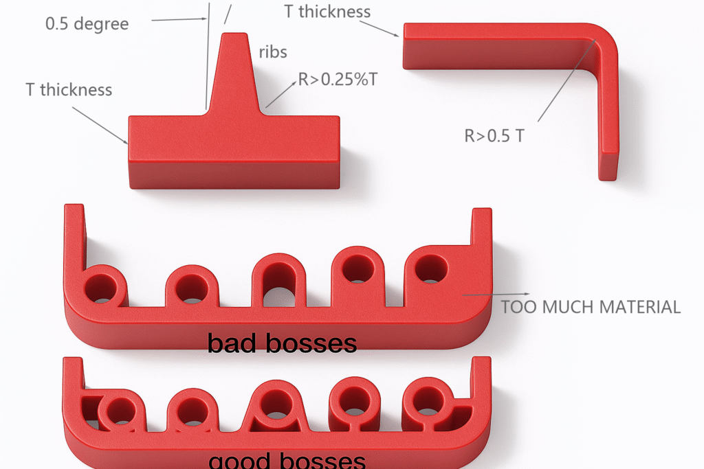
1. Wall Thickness, Ribs, and Bosses
In the last lesson, we set our nominal wall to 2.5 mm and the walls of our ribs and screw boss to ~1.5 mm (60% of nominal).
The DFM Check: Is there a risk of sink marks on the Class-A surface opposite the screw boss, even with the 60% rule?
- Analysis: The junction where the boss and support ribs meet the main wall creates a localized mass of material. While we've thinned the walls, this junction is still thicker than the surrounding 2.5 mm nominal wall. This "hotspot" will cool slower and shrink more, pulling on the A-surface.
- Risk: A visible sink mark on the beautiful, textured surface the customer sees and touches.
- Mitigation: The design is a good compromise, but in a formal DFM review, we would flag this as a risk. We might ask the mold-flow analyst to simulate the sink and confirm its severity. The solution is often in process control (adjusting packing pressure) rather than further design changes, but we must identify the risk first.
2. Undercuts and Side-Actions
Our grab handle design includes a cantilever snap-fit. This feature creates a significant manufacturing challenge.
The DFM Check: The hook on our snap-fit is an undercut.
- Analysis: An undercut is any feature that prevents the part from being directly ejected from the mold cavity in the main pull direction. The hook of our snap-fit would catch on the mold steel.
- Risk: The part cannot be ejected without breaking the part or the mold.
- Mitigation: This is where DFM provides huge value by forcing a decision between tooling complexity and design changes.
The video below clearly defines undercuts and outlines the primary engineering solutions.
Injection Molding - Undercuts (How to Avoid and Design)
This video from Protolabs is an excellent, concise guide to dealing with undercuts, which are a major cost and complexity driver in tool design.
First, watch the definition of an undercut to solidify your understanding: What is an undercut. Next, review the main solution categories: Four solutions. Pay close attention to the two most relevant solutions for our snap-fit: Side actions/cores, which are mechanical slides in the mold. Shut-offs, which are a clever design-based solution. Finally, watch the practical demo showing how to modify a part in CAD to create a shut-off condition, eliminating the need for a side-action.
Your Challenge:
For our grab handle's snap-fit, a side-action would add significant cost, complexity, and maintenance to the mold. A "shut-off" is a much more elegant and cost-effective solution.
- Based on the video's demonstration, how would you modify the grab handle design to create an opening or "window" that allows the mold steel to "shut off" under the snap-fit hook, thereby forming the feature without a mechanical slide? Describe the change you would make.
3. Gate Location, Weld Lines, and Venting
How and where we inject plastic into the part is a critical DFM consideration.
The DFM Check: Where should we place the gate, and where will the weld lines form?
- Analysis: The gate is the opening through which plastic enters the mold cavity. It leaves a small cosmetic blemish (vestige) that must be hidden. The weld line is the line formed when two or more plastic flow fronts meet. Weld lines are cosmetically undesirable and can be structurally weak.
- Gate Location: For the grab handle, we should gate into a non-cosmetic area. A common strategy is to use an edge gate on one of the ends that will be covered by an escutcheon or trim piece.
- Weld Line Prediction: If we gate from one end, the plastic flows to the other end. If we put a hole (like our screw boss) in the flow path, the plastic will flow around it and meet on the other side, creating a weld line. We must ensure this weld line is not in a high-stress area or on a visible surface.
- Venting: As plastic fills the mold, the air inside must escape. If it can't, it gets compressed, heats up, and causes burn marks (the diesel effect). Vents are tiny channels (0.02-0.05 mm) cut into the parting line of the mold. The DFM review must ensure that vents are planned for the last places to fill—typically opposite the gate.
This real-world case study highlights how a poor gate design led to product rejection.
Automotive Interior Door Handle Manufacturing & Injection Molding
This case study from FirstMold describes how they solved moldability issues for a client after a previous supplier failed. It provides direct insight into how DFM issues manifest as real-world production problems.
Read the sections titled "Concerns and Challenges" and "Solution". Note the specific issues found in the preliminary diagnosis: dimensional tolerance failure, mold alignment issues, and an "unreasonable gate design" that caused flow marks. This underscores the importance of getting the gate and flow path right from the start.
Your Turn: Perform a DFM Review
You've applied the basic rules and have now been introduced to a more systematic DFM review process. Let's put it into practice.
Consider our grab handle design, incorporating the refinements from the previous lesson (2.5 mm wall, 1.5 mm ribs, draft, and fillets). Using the principles we've discussed today:
- Identify the top 3 potential moldability issues with the design.
- For each issue:
- Name the specific manufacturing risk (e.g., sink mark, undercut, weld line, etc.).
- Describe the potential negative consequence (e.g., poor appearance, high tool cost, part failure).
- Propose a specific design modification or tooling strategy to mitigate the risk.
Think critically. I expect you to address the undercut on the snap-fit as one of the issues. What are two others?
Conclusion
Today, we transitioned from being a designer to being a manufacturing detective. A DFM review is not about finding fault; it's about proactively identifying and mitigating risk. By using a systematic checklist and thinking through the entire molding process—from filling to cooling to ejection—we can create designs that are not only functional and aesthetic but also robustly manufacturable.
Key Takeaways:
- DFM is a Systematic Process: It uses a structured approach, like a checklist, to analyze a design's manufacturability before tooling begins.
- Think Like the Plastic: Anticipate flow paths, weld lines, air traps, and hot spots.
- Undercuts Drive Cost: Features like our snap-fit require careful consideration. Designing out the need for a side-action (e.g., with a shut-off) is a high-impact DFM win that reduces tool cost and improves reliability.
- Gating is a Strategic Decision: Gate location affects cosmetic appearance (vestige) and structural integrity (weld lines). This must be defined during the design phase.
In our next lesson, we will take the risks we've identified today and formalize them in a Design Failure Mode and Effects Analysis (DFMEA). This will allow us to quantify the risks and track our actions to mitigate them—a core activity for any lead engineer.
Can't find a good explanation? Sign up and we'll make it for you
Sign up