
Welcome back! In our last lesson, we explored the heart's internal electrical conduction system and saw how the sequence of depolarization and repolarization creates the P, QRS, and T waves, which in turn drive the mechanical pumping of the cardiac cycle.
This lesson directly follows up on that by addressing the learning outcome: Explain Einthoven's triangle and the configuration of the 12-lead ECG system. We will move from the heart's internal wiring to the external measurement system used to capture its electrical signature. You'll learn why we place electrodes on specific points of the body to create different "electrical views" of the heart.
Understanding this is not just crucial for your university exams, but it also provides a fundamental principle for your work at Neuraease. While a wearable device doesn't use a full 12-lead system, the concept of a lead as a specific vector measurement between two points is identical. Optimizing electrode placement in a wearable to get a strong, clear R-peak for HRV analysis is a direct application of the principles we'll cover today.
The Challenge: Viewing the Heart from the Outside
In the previous lesson, we saw that the heart's electrical activity is a three-dimensional event. To diagnose problems effectively, we need to observe this activity from multiple angles. Since placing electrodes directly on the heart is not feasible for routine diagnostics, we use the skin's surface. The body, being composed largely of saltwater, is an excellent electrical conductor, allowing us to pick up these tiny cardiac potentials from the limbs and chest.
An electrode is the conductive pad attached to the skin. A lead is not the physical wire, but rather the specific view of the heart's electrical activity created by measuring the voltage difference between two or more electrodes.
The Frontal Plane: Einthoven's Bipolar Limb Leads
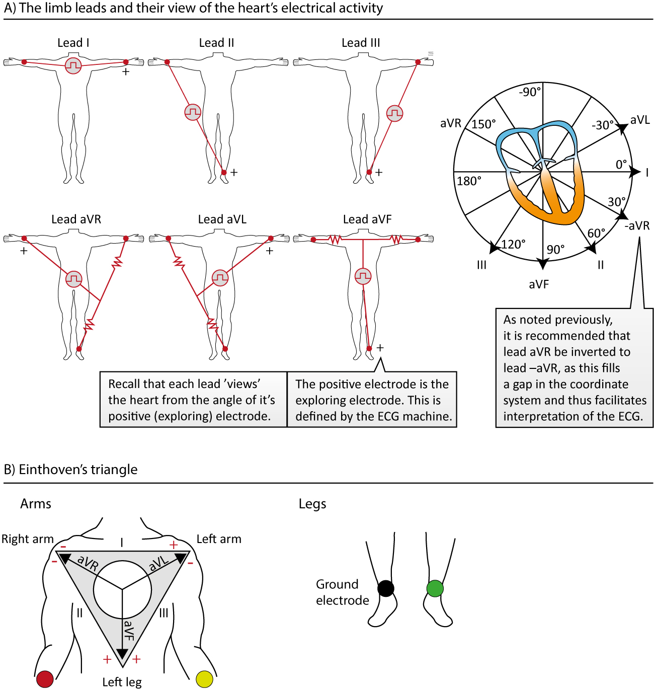
The foundation of modern ECG was laid by Willem Einthoven. He established that by placing electrodes on the right arm (RA), left arm (LA), and left leg (LL), we could create an imaginary triangle around the heart. This is known as Einthoven's Triangle. A fourth electrode is placed on the right leg (RL) to serve as a ground reference to reduce noise.
From these three electrodes, we can derive the first three leads, called the bipolar limb leads, because they measure the voltage difference between two specific points:
- Lead I: Measures the potential difference between the left arm and the right arm. . It provides a "view" from left to right across the heart (0° axis).
- Lead II: Measures the potential difference between the left leg and the right arm. . It provides a "view" from the top-right to the bottom-left (+60° axis).
- Lead III: Measures the potential difference between the left leg and the left arm. . It provides a "view" from the top-left to the bottom-left (+120° axis).
These three leads are mathematically related by Einthoven's Law, which states that the voltage of Lead II is the sum of the voltages of Leads I and III at any given instant:
This relationship is a direct consequence of Kirchhoff's voltage law applied to the circuit formed by the three leads.
The following video provides an excellent animated explanation of how these bipolar leads are formed.
From Basics of 12 Lead ECG to How Waves are Produced: Everything about Normal Electrocardiogram
The video 'From Basics of 12 Lead ECG...' by Nonstop Neuron clearly visualizes how the bipolar limb leads form Einthoven's triangle.
Please watch from 09:07 to 11:39. This section explains the standard bipolar limb leads (I, II, III), their orientation, and how they form Einthoven's triangle. It also clarifies the practical placement of electrodes on the wrists and ankle.
Expanding the Frontal View: Augmented Unipolar Leads
Einthoven's three leads give us three views of the heart in the frontal (vertical) plane. To get a more complete picture, we can cleverly use the same three limb electrodes to create three more leads. These are called augmented unipolar leads.
They are considered "unipolar" because they use a single positive (exploring) electrode, and the negative reference is a composite point created by averaging the signals from the other two limb electrodes. This reference point, known as Wilson's Central Terminal (WCT), approximates the electrical center of the heart.
The three augmented leads are:
- aVR (augmented Voltage Right arm): The positive electrode is on the right arm. It views the heart from the upper right (-150°).
- aVL (augmented Voltage Left arm): The positive electrode is on the left arm. It views the heart from the upper left (-30°).
- aVF (augmented Voltage Foot): The positive electrode is on the left leg. It views the heart from directly below (+90°).
Let's continue with the same video to see how these leads are derived.
From Basics of 12 Lead ECG to How Waves are Produced: Everything about Normal Electrocardiogram
Continuing with the 'Nonstop Neuron' video, the next segment explains the augmented unipolar leads.
Watch from 11:39 to 14:26. Focus on how aVR, aVL, and aVF are created using one limb as the positive electrode and a combination of the other two as the negative reference.
Together, the three bipolar leads and the three augmented leads give us six views of the heart in the frontal plane, spaced 30 degrees apart. This provides a detailed picture of electrical activity moving up, down, left, and right.

The Horizontal Plane: Precordial (Chest) Leads
The six limb leads give us an excellent view of the heart in the vertical plane, but they tell us little about electrical activity moving front-to-back. To get this third dimension, we place six more electrodes directly on the chest wall. These create the precordial leads, labeled V1 through V6.
Like the augmented leads, these are unipolar. Each of the six chest electrodes acts as a positive (exploring) electrode, and they are all measured against the same reference: Wilson's Central Terminal (the average of RA, LA, and LL).
The standard placement for these leads is critical for consistency:
- V1 & V2: Placed on either side of the sternum in the 4th intercostal space. They view the septum.
- V3 & V4: Placed over the anterior wall of the left ventricle.
- V5 & V6: Placed further to the left, viewing the lateral wall of the left ventricle.
From Basics of 12 Lead ECG to How Waves are Produced: Everything about Normal Electrocardiogram
The final set of leads, the precordial leads, give us our view in the horizontal plane. The 'Nonstop Neuron' video concludes by explaining their placement and function.
Now watch from 14:26 to 15:48. This section shows the anatomical placement of the six chest leads (V1-V6) and explains how they provide a transverse (horizontal) view of the heart.
Test your understanding!
A standard 12-lead ECG is generated using 10 electrodes. Can you list them?
Show answer
The 10 electrodes are:
- Right Arm (RA)
- Left Arm (LA)
- Left Leg (LL)
- Right Leg (RL - this is the ground electrode and not used for deriving leads)
- V1
- V2
- V3
- V4
- V5
- V6
The 12 leads are derived computationally from the signals picked up by these electrodes.
Putting It All Together: The 12-Lead System
The standard 12-lead ECG is the combination of these three lead groups, created historically by Einthoven, Goldberger, and Wilson.
- 6 Limb Leads (Frontal Plane):
- 3 Bipolar: I, II, III
- 3 Augmented Unipolar: aVR, aVL, aVF
- 6 Chest Leads (Horizontal Plane):
- 6 Unipolar: V1, V2, V3, V4, V5, V6
This combination gives a comprehensive 3D view of the heart's electrical activity, allowing clinicians to localize abnormalities with remarkable precision. For a concise summary of how these pieces fit together, I recommend this short article.
Lead systems – how an ECG works
The article 'Lead systems – how an ECG works' from Cardiosecur provides a great historical summary of how the 12-lead ECG came to be.
Please read the sections titled 'Einthoven’s Lead System', 'Goldberger’s Lead System', 'Wilson’s Lead System', and '12-lead ECG'. These sections concisely attribute each set of leads to its creator and define the final 12-lead system as the combination of all three.
Conclusion
In this lesson, we demystified the configuration of the 12-lead ECG. We've seen that it's not about 12 separate pairs of wires, but a clever system for creating 12 different electrical viewpoints using just 10 electrodes.
Key Takeaways:
- Einthoven's Triangle is the geometric basis for the first three bipolar limb leads (I, II, III), which measure potential differences between the right arm, left arm, and left leg.
- The augmented unipolar limb leads (aVR, aVL, aVF) use the same three limb electrodes to create three additional views in the frontal plane.
- The six precordial (chest) leads (V1-V6) provide a view of the heart's electrical activity in the horizontal plane.
- The complete 12-lead ECG combines these two sets of leads (6 limb + 6 chest) to provide a comprehensive 3D assessment of the heart's electrical function.
Preview of the Next Lesson:
Now that we know what we want to measure and from where, the next logical question is how do we build the machine to do it? In our next lesson, we will address the learning outcome: Design a complete ECG acquisition system, specifying amplifier, filter, and safety requirements. We will dive into the practical electronic design, covering topics like instrumentation amplifiers, filtering noise, and ensuring patient safety—topics that align perfectly with your ECE background.
Can't find a good explanation? Sign up and we'll make it for you
Sign up