
Hello! Welcome to your fourth lesson in the thermodynamics module.
In the last lesson, we established the fundamental principle of energy conservation: the First Law of Thermodynamics, . We defined internal energy () as the energy a system has, and heat () and work () as energy in transit. We also locked in the critical sign conventions for these energy transfers.
Today, we will put this law to work. The goal of this lesson is to apply the First Law of Thermodynamics to analyze closed systems, which are systems with a fixed mass, often called non-flow systems. We'll examine what the First Law tells us under different process conditions, laying the analytical groundwork for understanding the real-world thermodynamic cycles that power aircraft engines.
1. The First Law for a Closed System
Let's begin by formally stating the First Law for a closed system. As a statement of energy conservation, it says that the net energy transferred to a system (as heat) must equal the energy that leaves the system (as work) plus the change in the system's total stored energy.
This section from the textbook 'Introduction to Aerospace Flight Vehicles' provides the complete form of the First Law for a closed system and breaks down the total energy term.
Please read the two subsections titled 'The First Law of Thermodynamics' and 'Closed System Form'. Focus on Equation (16) and how the total energy E in Equation (17) is composed of internal, kinetic, and potential energy.
The full equation for the change in total energy () is:
Where .
In many practical thermodynamics problems, the system as a whole is stationary, meaning there is no change in its overall velocity or elevation. In these cases, the changes in macroscopic kinetic energy () and potential energy () are zero. The First Law then simplifies to the form we saw in the last lesson, dealing only with the change in internal energy:
This is the central equation we will be applying today. It links the change in a system's state (represented by ) to the energy transfers ( and ) that caused the change.
2. Common Non-Flow Processes
The amounts of heat () and work () transferred depend on the path the process takes between its initial and final states. We will now look at four common, idealized paths for processes in closed systems. A piston-cylinder device is an excellent physical model for visualizing these.
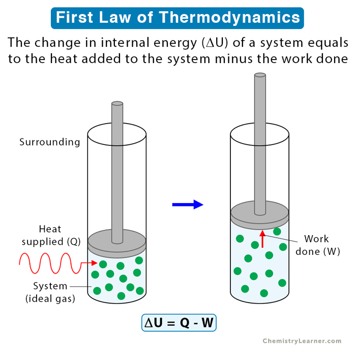
The resource below provides an excellent summary of the equations for work, heat, and internal energy for these processes when the working substance is an ideal gas.
This PDF chapter on the 'First Law of Thermodynamics' contains a concise but comprehensive section on its application to non-flow processes. It provides the key formulas you'll need.
Please read Section 4.9, 'Application of First Law... to Non-Flow or Closed System'. Then, study the 'Summary of Processes' table (Table 4.1). Focus on understanding the formulas for each of the following processes: Constant Volume (Isochoric): Note that work done is zero. Constant Pressure (Isobaric): Note how heat transfer relates to the change in enthalpy (Q = \Delta H). Constant Temperature (Isothermal): Note that for an ideal gas, \Delta U = 0. Reversible Adiabatic: Note that heat transfer is zero (Q=0). Treat this as your 'formula sheet' for this part of the course. You don't need to memorize the derivations, but you should understand the result for each process type.
3. Applying the First Law: Worked Examples
Now let's see how this framework is used to solve real problems. The following videos walk through the complete analysis of two common scenarios. They demonstrate the systematic approach required:
- Sketch the system and identify the process.
- State your assumptions.
- Write down the relevant form of the First Law.
- Determine the properties at each state (often using thermodynamic tables).
- Calculate the unknown quantities (, , or ).
Example 1: Constant Volume Process (Rigid Tank)
This first example involves heating a refrigerant in a sealed, rigid tank. This is a classic isochoric (constant volume) process. Because the volume doesn't change, the boundary work is zero, which simplifies the First Law analysis considerably.
Thermodynamics: 1st Law for Closed Systems (8 of 25)
This video from 'CPPMechEngTutorials' provides a very detailed walkthrough of a constant volume problem. It shows the full professional workflow, from problem setup to using property tables.
Watch from 02:33 to 33:14. This is a detailed segment, so focus on the method: Problem Setup (until ~11:20): Pay close attention to how the problem statement 'sealed, rigid vessel' immediately tells you that V = ext{constant} and W_{boundary} = 0. Notice how the First Law simplifies to Q = \Delta U. Finding Properties & Solving (from ~11:20): Observe the process of using the property tables to find the initial and final internal energies (u_1 and u_2). The detailed steps for interpolation are good to see, as this is a common requirement.
Example 2: Constant Pressure Process (Piston-Cylinder)
Our second example involves heating a refrigerant in a piston-cylinder device. This is a classic isobaric (constant pressure) process. Here, the volume changes, so there is boundary work to calculate.
This problem uses refrigerant R-134a, just like the previous one, so the process of using the tables will feel familiar. The key difference is the calculation of work and its inclusion in the First Law energy balance.
Thermodynamics: 1st Law for Closed Systems, Specific Heats (9 of 25)
This next video from the same channel analyzes a constant pressure expansion in a piston-cylinder device. This demonstrates how to handle boundary work.
Watch the first example in the video, from the beginning to 23:47. Focus on: How the problem is identified as a constant pressure process. The formula used to calculate boundary work for a constant pressure process: W = p(V_2 - V_1). How the full First Law equation (Q = \Delta U + W) is used to find the total heat transfer.
Test your understanding!
A closed, rigid container holds 0.5 kg of air. A paddle wheel stirs the air, doing 10 kJ of work on it. During this process, 2 kJ of heat is lost to the surroundings. What is the change in the specific internal energy () of the air in kJ/kg?
Show answer
-
Identify the System and Process:
- System: The air in the container.
- Process: This is a constant volume process because the container is rigid. However, there are two energy interactions: paddle-wheel work and heat transfer.
-
Assign Signs to Q and W:
- Heat is lost from the system: .
- Work is done on the system by the paddle wheel: . Note that even though the volume is constant, this is not boundary work, so W is not zero.
-
Apply the First Law:
This is the change in the total internal energy for the 0.5 kg of air. -
Calculate Specific Internal Energy Change:
The question asks for the specific internal energy change (), which is per unit mass.
The specific internal energy of the air increases by 16 kJ/kg.
Conclusion
In this lesson, you have learned how to apply the First Law of Thermodynamics as a practical tool for analyzing energy changes in closed systems. By combining the core equation with the specific constraints of common processes, you can now solve for unknown heat, work, or internal energy changes.
Key Takeaways:
- The simplified First Law for stationary closed systems is .
- Isochoric (constant volume) process: No boundary work is done (), so .
- Isobaric (constant pressure) process: Work is , and heat transfer is equal to the change in enthalpy, .
- Isothermal (constant temperature) process: For an ideal gas, , so .
- Adiabatic process: No heat is transferred (), so .
- A systematic approach involving sketching the system, identifying the process, applying the First Law, and using property data is essential for solving problems.
Preview of the Next Lesson:
The examples today used refrigerants and steam, which required looking up properties in tables. While powerful, this can be cumbersome. In our next lesson, we will focus specifically on systems containing an ideal gas. We will derive simplified equations for each of the four processes we studied today, allowing for more direct calculations without needing extensive tables. This will be a significant step toward analyzing the ideal gas cycles, like the Brayton cycle, that model jet engines.
Can't find a good explanation? Sign up and we'll make it for you
Sign up