
Hello! Welcome back to our course on Medical Instrumentation.
In our last lesson, we explored the world of non-invasive blood pressure measurement, dissecting the auscultatory and oscillometric methods. We learned that while these are excellent for routine checks, they provide only intermittent snapshots and can be less reliable in critically ill patients.
Today, we transition to the "gold standard" of hemodynamic monitoring. This lesson is designed to help you describe the use of catheter-transducer systems for invasive hemodynamic monitoring. We will examine the complete system, from the catheter inside the patient to the waveform on the screen. We'll cover the engineering principles that ensure accuracy and look at how these systems are used to gain deep insights into a patient's cardiovascular status.
While your work at Neuraease focuses on non-invasive wearables, understanding the principles behind this high-fidelity, invasive gold standard provides a crucial benchmark for signal quality, artifact management, and transducer function—concepts that are universal in instrumentation.
1. The Anatomy of an Invasive Monitoring System
At its core, an invasive pressure monitoring system is a chain that converts a physiological pressure into an electrical signal. It consists of four key parts:
- The Sensor Interface: A catheter placed inside a blood vessel (e.g., an artery or a central vein).
- The Transmission Link: Rigid, non-compliant tubing filled with a saline solution.
- The Transducer: A device that converts the mechanical pressure wave into an electrical signal.
- The Processor & Display: An electronic monitor that processes the signal and displays it as a waveform and numerical values.
Let's begin with a video that clearly explains how these components work together in the context of an invasive arterial line.
Invasive Arterial Blood Pressure Measurement
This video from The Alfred Intensive Care Academic Centre provides a concise breakdown of the components of an invasive pressure monitoring system and gives a great explanation of how a pressure transducer works.
Watch from 00:27 to 02:55. Focus on: The four main components of the system. The role of the catheter and the importance of stiff, fluid-filled tubing. How the transducer—using a diaphragm, strain gauges, and a Wheatstone bridge—converts pressure into an electrical signal.
As the video showed, the pressure transducer is the heart of the system. The pressure wave from the patient travels through the fluid column and flexes a small diaphragm inside the transducer. This mechanical movement is what needs to be converted into an electrical signal.
This is accomplished using strain gauges arranged in a Wheatstone bridge circuit.
- A strain gauge is a resistor whose resistance changes when it is stretched or compressed.
- By bonding strain gauges to the diaphragm, the diaphragm's flexion changes their resistance.
- The Wheatstone bridge is a highly sensitive circuit for measuring small changes in resistance. The change in resistance from the strain gauges unbalances the bridge, producing an output voltage that is directly proportional to the applied pressure.
This application is a classic example of the kind of transducer principles you would have encountered in your ECE studies.
2. Ensuring Accuracy: Calibration and Dynamic Response
A system is only as good as its accuracy. For a catheter-transducer system, achieving an accurate reading involves two critical steps: static calibration and ensuring a proper dynamic response.
Static Calibration: Leveling and Zeroing
Before we can trust a measurement, we must establish a correct reference point. This involves two actions:
- Leveling: The transducer must be positioned at the same vertical height as the tip of the catheter inside the patient. For cardiovascular measurements, this reference point is called the phlebostatic axis (approximating the level of the right atrium). If the transducer is too low, the weight of the fluid column (hydrostatic pressure) will falsely elevate the reading. If it's too high, the reading will be falsely low. A 10 cm error in height can change the reading by over 7 mmHg!
- Zeroing: The system must be referenced to a "zero" pressure. This is done by opening a stopcock on the transducer to the surrounding air, telling the monitor to treat atmospheric pressure as the zero point. All subsequent blood pressure readings are then measured relative to this atmospheric pressure baseline.
The following reading provides an excellent practical summary of these crucial setup steps.
Arterial Pressure Monitoring - StatPearls - NCBI Bookshelf - NIH
The 'StatPearls' article offers a clear, practical guide on the importance of properly setting up the transducer system to ensure accurate measurements.
Please read the section titled 'Nursing, Allied Health, and Interprofessional Team Monitoring.' Start from the paragraph 'To accurately measure arterial blood pressure...' and read down to the end of the section ('...reflect the patient's actual arterial pressure accurately.'). Focus on the concepts of leveling the transducer, the effect of incorrect positioning, the process of zeroing, and the 'square wave test' for checking the system's dynamic response.
Dynamic Response: Damping and Resonance
An arterial pressure waveform is a complex signal with a rapid upstroke and other high-frequency components. The measurement system must be able to reproduce this waveform faithfully without distorting it. This is known as its dynamic response. The two main enemies of a good dynamic response are resonance and damping.
This is a classic second-order system problem, much like an RLC circuit in electronics. The mass of the fluid in the tubing and the compliance (stretchiness) of the tubing and transducer diaphragm give the system a natural resonant frequency.
Let's return to our first video for a great explanation of these concepts.
Invasive Arterial Blood Pressure Measurement
The system itself can distort the pressure waveform through resonance or damping. This next segment of the video explains these critical concepts.
Watch from 02:55 to 07:15. Don't worry about the detailed math. Focus on understanding: Resonance: Why the system's natural frequency must be much higher than the heart rate to avoid 'ringing' and overestimation of pressure. Damping: What it is, and the visual difference between an under-damped (overshoots, high systolic) and an over-damped (blunted waveform, low systolic) system.
To summarize the key points:
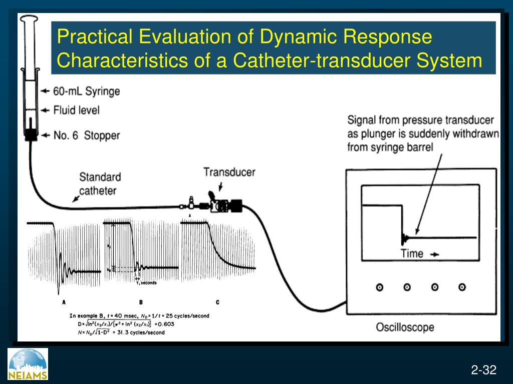
- Under-damped System: There is too little damping, allowing the system to oscillate or "ring" at its natural frequency. This leads to a systolic pressure that is falsely high (overshoot) and a diastolic pressure that may be falsely low. The waveform will show sharp peaks and multiple oscillations after the dicrotic notch.
- Over-damped System: There is too much damping, making the system sluggish. This can be caused by air bubbles, clots, or overly compliant tubing. The system cannot respond quickly enough to the rapid pressure changes, resulting in a blunted, smoothed-out waveform with a falsely low systolic pressure.
- Optimally Damped System: This is the ideal balance, providing the most accurate waveform representation. As mentioned in the reading, this is checked clinically with a square wave test (or fast-flush test), which should result in one or two oscillations before returning to baseline.
Test your understanding!
An ICU patient has an arterial line for blood pressure monitoring. The nurse notes that the waveform on the monitor shows a very sharp, narrow peak, and the systolic reading is 175 mmHg, which seems unusually high for this patient. However, the Mean Arterial Pressure (MAP) is in the expected range.
- What is the most likely issue with the measurement system?
- What are some potential physical causes for this issue?
- If the nurse then notices the transducer was mistakenly placed on the bedrail, about 15 cm below the patient's heart, how would this positioning error affect the readings in addition to the problem in question 1?
Show answer
- The most likely issue is an under-damped system. The sharp peak (systolic overshoot) and ringing, combined with a plausible MAP, are classic signs of resonance in the system.
- Potential causes for an under-damped system include using very stiff, rigid tubing, catheters that are too wide or short, or conditions like high cardiac output in the patient.
- Positioning the transducer 15 cm below the heart level will introduce a positive hydrostatic pressure error. This will cause the entire waveform—and all pressure values (systolic, diastolic, and mean)—to be falsely elevated. A rough estimate for this error is about 1.1 mmHg per cm, so a 15 cm error would falsely add approximately 11 mmHg to the already overestimated systolic reading.
3. Key Applications: Arterial and Pulmonary Artery Catheters
Now that we understand the "how," let's look at the two most common uses of these systems.
Arterial Line
As we've seen, this involves placing a catheter in a peripheral artery (like the radial artery in the wrist). Its purpose is to provide continuous, beat-to-beat monitoring of systemic arterial blood pressure. This is indispensable in the ICU for managing unstable patients and precisely titrating powerful medications that affect blood pressure.
Pulmonary Artery (PA) Catheter
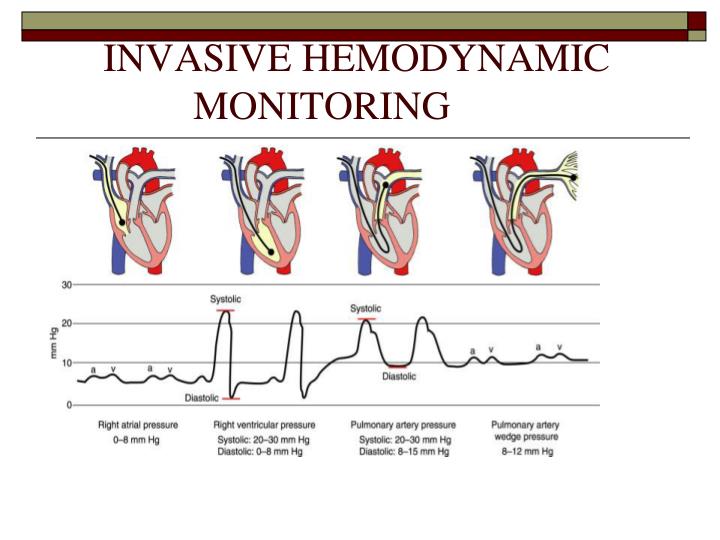
The PA catheter (also known as a Swan-Ganz catheter) is a far more advanced diagnostic tool. This long, flexible catheter is inserted into a large central vein and threaded through the right side of the heart to sit in the pulmonary artery. It has multiple ports and a balloon at its tip, allowing it to measure pressures at different points along its path.
The following image provides a perfect overview of its journey and the corresponding pressure waveforms.
To understand the power of this device, let's watch one final video.
Invasive Monitoring | Hemodynamics (Part 5)
The Pulmonary Artery (PA) or Swan-Ganz catheter is a powerful application of the catheter-transducer principle. This video explains its path through the heart and the different crucial pressures it can measure, giving a complete picture of a patient's hemodynamic status.
Watch from 17:39 to 23:45. Focus on: The path the catheter takes from a central vein into the pulmonary artery. The different pressures measured: CVP/RAP, PAP, and the Pulmonary Capillary Wedge Pressure (PCWP). The clinical significance of these pressures (e.g., PCWP as an indirect indicator of left heart function).
The PA catheter provides a comprehensive hemodynamic profile by measuring:
- Right Atrial Pressure (RAP) or Central Venous Pressure (CVP): An indicator of right ventricular preload (the volume filling the heart before it contracts).
- Pulmonary Artery Pressure (PAP): The blood pressure in the lungs.
- Pulmonary Artery Wedge Pressure (PAWP): By inflating the balloon, the catheter tip is isolated from the pressure of the right heart and instead "looks ahead" through the pulmonary capillaries to the left atrium. This gives an excellent indirect measurement of left atrial pressure, which is a key indicator of left ventricular preload and function.
This single device allows clinicians to separately assess the function of the right and left sides of the heart.
Conclusion
In this lesson, we have moved from non-invasive snapshots to the continuous, high-fidelity world of invasive hemodynamic monitoring. You can now describe the complete catheter-transducer system and the critical principles that govern its accuracy.
Key Takeaways:
- Invasive monitoring systems use a catheter, fluid-filled tubing, and a pressure transducer to convert a physiological pressure into a continuous electrical signal.
- The transducer typically uses a strain gauge and Wheatstone bridge to detect the flexing of a diaphragm.
- System accuracy depends critically on static calibration (leveling to the phlebostatic axis and zeroing to atmospheric pressure) and an optimal dynamic response.
- An under-damped system will overestimate systolic pressure, while an over-damped system will underestimate it.
- Arterial lines measure systemic blood pressure, while Pulmonary Artery catheters provide a comprehensive profile of pressures within the right heart and pulmonary circulation, including an estimate of left heart filling pressure (PAWP).
Preview of the Next Lesson:
Pressure is just one half of the hemodynamic equation; the other is flow. In our next lesson, we will investigate how we measure the movement of blood itself. We will explore the principles behind electromagnetic and ultrasonic Doppler techniques for blood flow measurement.
Can't find a good explanation? Sign up and we'll make it for you
Sign up