
Good morning. In our last session, we conducted a DFMEA to systematically identify and prioritize potential failures in our bracket design. We concluded that the highest risks are fracture at the bends and misalignment of mounting holes due to springback. This analysis tells us what to control; today, we will define exactly how to control it.
This lesson bridges the gap between risk analysis and production reality. Our objective is to define a complete Geometric Dimensioning and Tolerancing (GD&T) scheme for the bracket. We will establish a robust datum reference frame and then apply position and profile tolerances to the critical features we identified in the DFMEA. This is the language used on engineering drawings to ensure that the part you designed is the part that gets manufactured and functions correctly.
1. The Foundation: Establishing the Datum Reference Frame (DRF)
Before we can control any feature, we must first establish a frame of reference. In GD&T, this is the Datum Reference Frame (DRF). Its purpose is to immobilize the part in all six degrees of freedom (three translations: X, Y, Z; and three rotations: about X, Y, Z) so that measurements are stable and repeatable. This is typically achieved using a 3-2-1 locating principle, where three datums (A, B, and C) are used in order of precedence.
For a comprehensive introduction to GD&T principles, including datums and the structure of feature control frames, the video "Understanding GD&T" is an excellent resource.
Watch this video from The Efficient Engineer to get a foundational understanding of GD&T concepts.
Focus on these two key segments: GD&T introduction: This section explains the purpose of GD&T and introduces the feature control frame. Datums explained: Pay close attention to how a primary, secondary, and tertiary datum are used to constrain the six degrees of freedom and create a DRF.
The selection of datum features is dictated by the part's function. We must ask: How does this part mount and interact with its environment? The most critical functional and stable surfaces should be chosen as datums.
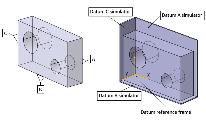
For our mounting bracket, the functional interfaces are clear:
- Primary Datum (A): The large, flat face that bolts to the vehicle body. This surface defines the primary orientation of the bracket. It's the most stable feature and constrains three degrees of freedom (translation along the Z-axis, rotation about the X and Y axes).
- Secondary Datum (B): A feature that stops the part from translating. For our bracket, the most reliable feature is one of the mounting holes. Using a hole's axis is more repeatable than using a stamped edge, which can have imperfections. This constrains two degrees of freedom (translation along X and Y axes).
- Tertiary Datum (C): A final feature to lock rotation. A second mounting hole serves this purpose perfectly, constraining the final degree of freedom (rotation about the Z-axis).
2. Controlling Location: Position Tolerance
The DFMEA highlighted the risk of hole misalignment, which could stop the assembly line—a costly failure. The Position tolerance is the primary tool for controlling the location of features of size, such as our mounting holes.
It defines a cylindrical tolerance zone around a feature's theoretically exact location, or "True Position." The feature's axis must lie entirely within this zone.
True Position – Position Tolerance | GD&T Basics
This article from GD&T Basics provides a detailed explanation of the Position tolerance.
Read the initial sections to understand the core concepts: Start with the Definition of True Position. Review the section on Application to see that it applies to features of size like holes. Study the Position Tolerance Zone section to understand how the datums and basic dimensions create the framework for the tolerance zone.
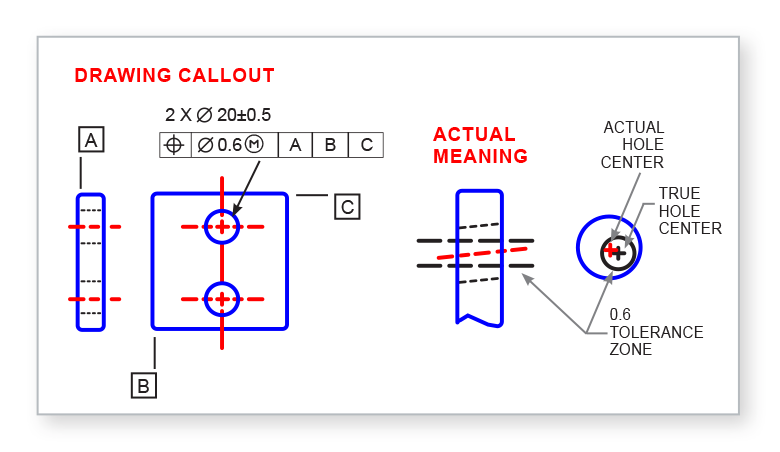
The Power of Material Modifiers: MMC
For features like clearance holes, we can add a powerful modifier to the position tolerance: Maximum Material Condition (MMC), denoted by an Ⓜ.
When a position tolerance is applied at MMC, it means the stated tolerance (e.g., Ø0.5) applies when the hole is at its smallest allowable size (its maximum material condition). If the hole is produced larger (departing from MMC), a bonus tolerance is added to the position tolerance.
Bonus Tolerance = (Actual Hole Size) - (MMC Hole Size)
This is a critical concept in automotive design. It guarantees that parts will assemble while giving the manufacturing team the largest possible tolerance, reducing cost and scrap.
To see how bonus tolerance works in practice, let's return to the "Understanding GD&T" video.
Watch these sections to understand Position tolerance and the functional benefit of MMC.
Position tolerance: This provides a concise explanation of how Position is defined using basic dimensions and a cylindrical tolerance zone. Bonus tolerance: This segment clearly explains the concept of MMC and how it allows for a bonus tolerance, which is key for manufacturability.
3. Controlling Form: Profile Tolerance
Our other high-risk failure was fracture at the bend. While bend radius and material choice are the primary mitigations, we must also ensure the manufactured bend has the correct shape and is in the right location. Irregularities in the bend's surface could create stress concentrations.
The Profile of a Surface tolerance is a versatile control perfect for this. It defines a uniform boundary along the true profile of a surface, within which the actual surface must lie. It can control a feature's size, location, orientation, and form simultaneously.
For our bracket, we can apply a Profile of a Surface tolerance to the large bent flanges, referencing our DRF (|A|B|C|). This ensures these complex surfaces are shaped correctly and positioned accurately relative to the mounting face. The "Understanding GD&T" video offers a quick look at this.
Watch this final segment on profile tolerances.
Profile tolerances: This introduces the concept of Profile of a Surface and Profile of a Line.
4. Your Task: Defining the GD&T Scheme
Let's now apply these concepts to our bracket. Based on our discussion, you will define the GD&T scheme.
1. Define the Datum Reference Frame:
Identify features on the bracket to serve as Datums A, B, and C. Justify your selection based on part function and stability for measurement.
- Datum A: ? (Primary, constrains 3 DOF)
- Datum B: ? (Secondary, constrains 2 DOF)
- Datum C: ? (Tertiary, constrains 1 DOF)
Challenge: Why is it generally preferable to use a hole for a secondary datum (Datum B) on a stamped part, rather than a long, straight edge?
2. Apply Position Tolerance to the Mounting Holes:
Assume the three mounting holes are Ø10.5 ± 0.2 mm. Their locations are defined by basic dimensions on the drawing. Write the complete Feature Control Frame to control their position.
- Select a reasonable tolerance value (e.g., Ø0.8).
- Include the MMC modifier.
- Reference your chosen DRF.
Challenge: You've specified the position tolerance at MMC. If a manufactured part has a hole measuring Ø10.6 mm, and your specified position tolerance is Ø0.8 at MMC, what is the total positional tolerance for that specific hole?
3. Apply Profile Tolerance to the Main Bend:
Write the Feature Control Frame to control the main bent surface of the bracket.
- Select a reasonable tolerance value (e.g., 1.0).
- Reference your DRF.
Challenge: By referencing the full DRF |A|B|C|, what aspects of the bent surface are you controlling with this single profile callout?
5. Case Study: GD&T on a Hinge Bracket
To see these principles applied in a complete, real-world example, we will review the GD&T scheme for a sheet metal hinge bracket. This case study directly mirrors our task.
GD&T : Applying GD&T scheme to a part in assembly - Hinge bracket
Watch this video from Mechademic to see a complete GD&T scheme applied to a sheet metal part.
Follow the instructor's logic through these steps: Datum A: Note the selection of the primary datum and the application of a form control (flatness) to refine it. Datum B: See how a specific hole is designated as the secondary datum. Datum C: Understand how the remaining holes create the tertiary datum. Controlling the Pinhole: Observe how the final, critical functional feature (the pinhole) is controlled using a position tolerance referenced to the full DRF (|A|B|C|).
This video provides an excellent template for how you will document your own GD&T decisions on the final 2D drawing.
Conclusion
In this lesson, we have established the critical link between design risk and manufacturing control. You have learned how to define a robust GD&T scheme that directly addresses the potential failure modes identified in our DFMEA.
Here are the key takeaways:
- A Datum Reference Frame (DRF), built on functional and stable features, is the foundation of any GD&T scheme.
- Position tolerance with MMC is the automotive industry standard for controlling features of size like mounting holes. It ensures assemblability while maximizing manufacturing tolerance.
- Profile of a Surface is a powerful and versatile control for ensuring the form and location of complex or critical surfaces, such as the bends in our bracket.
- A well-defined GD&T scheme is not arbitrary; it is a precise engineering specification designed to mitigate functional risk.
In our final lesson for this project, we will take the GD&T scheme defined today and create a complete 2D production drawing for the bracket, including all views, dimensions, and the flat pattern required for manufacturing.
Can't find a good explanation? Sign up and we'll make it for you
Sign up