
Good morning. In our previous session, we established a robust GD&T scheme for our bracket, defining datums and applying position and profile tolerances to mitigate the key risks identified in our DFMEA. We now have a clear plan for what needs to be controlled.
Today, we will execute that plan by creating the final deliverable for any design engineer: the 2D production drawing. This document is the legal and technical contract with manufacturing. It must be clear, complete, and unambiguous. Our objective is to produce a complete 2D drawing for the bracket, incorporating all necessary views, dimensions, the GD&T scheme we developed, and a flat pattern view. This process translates our 3D design intent into a 2D format that guides fabrication and inspection.
1. The Anatomy of a Sheet Metal Drawing
A drawing for a stamped component requires more than just standard orthographic views. It must represent the part in both its final (formed) state and its initial (flat) state.
A complete drawing package typically includes:
- Orthographic Views: Front, top, and side views to define the geometry of the formed part.
- Isometric View: A 3D view to provide visual clarity of the final part.
- Flat Pattern View: A critical view showing the part's 2D profile before bending. This is essential for quoting, material nesting on the sheet, and programming the cutting operation (laser, turret punch).
- Dimensions & Tolerances: All necessary dimensions and GD&T callouts to control the part's geometry and function.
- Notes: Information about material, thickness, finish, and other general requirements.
The following article provides an excellent overview of these components.
Top Tips for Creating Better Sheet Metal Part Drawings - Five Flute
Read the introduction and the first few sections of this article from Five Flute.
Focus on the sections titled: Sheet metal specific drawing items: This will introduce the key elements we'll discuss. Flat pattern views: Pay attention to why this view is included and the important caution that the CAD-generated flat pattern is a reference, as manufacturing processes can affect the final required shape. Complete, realistic, and properly formatted dimensioning: This sets the stage for our dimensioning strategy. Don’t go crazy with GD&T: This reinforces our approach from the last lesson—using GD&T strategically where it adds functional value.
This example drawing shows how these elements come together to create a clear and comprehensive manufacturing document.
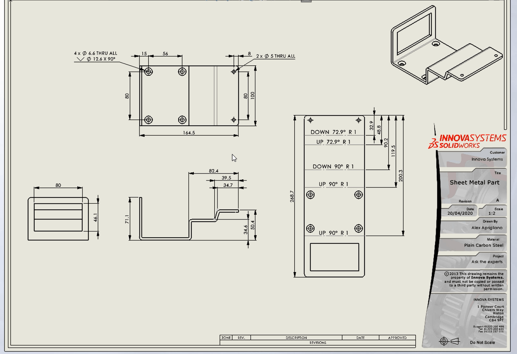
2. Generating the Flat Pattern View (CATIA Logic)
In CATIA V5, the flat pattern is created within the Generative Drafting workbench. The key is to use the Unfolded View command, which is specifically designed for sheet metal parts. This command projects the unbent state of the part onto the drawing sheet.
While the command is straightforward, displaying the necessary bend line information (bend direction, angle, and radius) requires a specific setup. This information is crucial for the press brake operator. The following video demonstrates this exact process.
Bend - Annotations - Catia v5 Training - Basics - Drafting
This tutorial from Wolfgang Walden CAD Training shows how to create an unfolded view with bend annotations in CATIA V5 Drafting.
Watch these key steps: Creating the unfolded view: See the basic command in action. Enabling bend annotations: This is the most critical part. It explains how to activate the generative view style needed to display bend data. Although you are using Onshape, understanding this CATIA-specific logic for customizing drawing views is important. Arranging annotations: Observe how the annotations are cleaned up for better readability.
3. Dimensioning and GD&T Application
With our views established, we can now apply dimensions and the GD&T scheme from our last lesson.
Dimensioning Strategy
For sheet metal, it is best practice to dimension to virtual sharps—the theoretical intersection points of the flat faces, as if the bend had no radius. This makes the drawing independent of the actual bend radius achieved in production, which can vary.
The article "Top Tips for Creating Better Sheet Metal Part Drawings" (resource LINK) illustrates this well in the image under the "Complete, realistic, and properly formatted dimensioning" section.
Applying GD&T
Now, we place the controls we defined previously onto the drawing views.
- Datum Feature Symbols: Attach the datum symbols for A, B, and C to the features we selected.
- Datum A symbol is placed on the edge view of the large mounting face or attached with a leader to the face itself in the isometric view.
- Datum B and Datum C symbols are attached to the respective mounting holes that we designated.
- Basic Dimensions: The X and Y locations of the mounting holes relative to each other and the datums must be defined using Basic Dimensions (dimensions enclosed in a box). These dimensions have no tolerance; they define the "True Position."
- Feature Control Frames:
- The Position tolerance FCF for the mounting holes is attached to the hole size dimension.
- The Profile of a Surface tolerance FCF for the bent flange is attached to the surface with a leader line.
This is what the CATIA Drafting workbench looks like when you are adding these annotations.

4. Critical Drawing Notes and Final Deliverables
The views and dimensions define the geometry, but the drawing notes provide the rest of the manufacturing specification. For our bracket, the following notes are mandatory:
- Material Specification: e.g.,
MATERIAL: DP 600 STEEL, THICKNESS 1.5mm. - Finish Specification: e.g.,
FINISH: E-COAT, BLACK, 20-30 MICRONS THICK. - General Tolerances: A note in the title block, such as
UNLESS OTHERWISE SPECIFIED, ALL DIMENSIONS ARE +/- 0.5mm. - Edge Condition: e.g.,
BREAK ALL SHARP EDGES R0.2 MAX. This is a safety and quality requirement. - Flat Pattern Reference: A note explicitly stating which external file contains the flat pattern, e.g.,
FLAT PATTERN FOR REFERENCE, SEE DXF FILE [FILENAME].DXF.
The Manufacturing Data Package
Finally, you will release a package of files to the supplier. This typically includes:
- The 2D Drawing: In PDF format, as the master document.
- The 3D Model: A neutral format like STEP, used for reference and fixture design.
- The Flat Pattern File: A 2D DXF or DWG file containing only the flat pattern geometry. This is used directly for CAM programming of the laser cutter or punch press.
Top Tips for Creating Better Sheet Metal Part Drawings - Five Flute
Review the final sections of the Five Flute article.
Focus on: Include common sheet metal specific information: This lists the critical notes we just discussed. File Preparation and Manufacturer Collaboration: This section details the standard file formats (PDF, STEP, DXF) expected by manufacturers.
5. Your Task: Finalize the Bracket Drawing
Based on today's lesson and our work in the previous session, you will now define the contents of the final drawing for our bracket.
Assume you have the 3D model of the bracket. Describe how you would create the final drawing by answering the following:
- View Layout: List the views you would create and briefly state the purpose of each (e.g., "Front View - to show the main bend profile").
- GD&T Placement: On which view(s) would you place the following controls, and how would you attach them?
- Datum A symbol
- Datum B & C symbols
- Position tolerance FCF for the mounting holes
- Profile of a Surface FCF for the main bent flange
- Critical Information: List three essential notes you would add to the drawing, specific to our sheet metal bracket.
Take your time to think through the placement of each item to ensure maximum clarity for the manufacturer.
Conclusion
Today, we have consolidated all of our design decisions, analysis, and geometric controls into a single, comprehensive document—the 2D engineering drawing. This is the culmination of the design process for this component.
Key Takeaways:
- A sheet metal drawing is unique due to the requirement of a flat pattern view in addition to standard orthographic and isometric views.
- CATIA's Generative Drafting workbench provides specialized tools like
Unfolded Viewto create these drawings. - Clear dimensioning (to virtual sharps), strategic GD&T, and comprehensive notes are essential for unambiguous communication with manufacturing.
- The final deliverable is a data package (PDF, STEP, DXF) where the 2D drawing serves as the master document.
This completes our deep dive into the design of a single stamped component. In our next module, we will scale up our focus to a multi-part Body-in-White (BIW) assembly and tackle the challenge of managing an Engineering Change Order (ECO).
Can't find a good explanation? Sign up and we'll make it for you
Sign up