
Good morning. In the last lesson, we conducted a Design for Manufacturing (DFM) review, scrutinizing our bracket design to anticipate stamping risks like springback and tearing. That proactive analysis was crucial, and today we will formalize it using an industry-standard risk management tool: the Design Failure Mode and Effects Analysis (DFMEA).
Our objective is to identify the top failure modes for the bracket, focusing specifically on risks originating from the stamping process and those that could impact vehicle assembly. The issues we identified in the DFM review—dimensional errors from springback, hole distortion, and potential cracks—will serve as direct inputs, transforming our qualitative concerns into a structured, quantifiable risk assessment.
1. Understanding the DFMEA Framework
A DFMEA is a systematic, team-based activity that analyzes a product design before it is released to production. Its purpose is to identify, prioritize, and mitigate potential design weaknesses. It is a core document within the APQP (Advanced Product Quality Planning) process and serves as a living record of your risk management decisions.
Since you have a foundational understanding of FMEA from your studies, we'll focus on its practical application in an automotive context. Let's start with a video that clearly defines the scope of FMEA and distinguishes between a Design FMEA (DFMEA) and a Process FMEA (PFMEA).
FMEA, the 10 Step Process to do an FMEA (PFMEA or DFMEA)
Watch the video "FMEA, the 10 Step Process" from CQE Academy to refresh your understanding of FMEA's role in risk management.
Focus on these two segments: What is an FMEA?: This section explains FMEA's purpose as a systematic risk management tool. DFMEA vs. PFMEA: Pay close attention to the distinction. Our focus today is purely on the DFMEA, which concerns product design features and their potential failures. The PFMEA, which analyzes the manufacturing process itself, would be the responsibility of the manufacturing engineering team, although they would use our DFMEA as a key input.
The Failure Chain: Cause, Mode, and Effect
The logic of an FMEA is built around the failure chain. Understanding this relationship is the key to performing an effective analysis.
- Failure Cause: The specific design deficiency or weakness that allows the failure to occur. Why does it fail?
- Failure Mode: The manner in which the component or system could fail to meet its design intent. How does it fail?
- Failure Effect: The consequence of the failure mode on the system, the vehicle, or the end-user. What happens when it fails?
A single cause can lead to a mode, which can have multiple effects. The AIAG & VDA FMEA Handbook provides a clear visualization of this concept.
AIAG & VDA Design Failure Mode and Effect Analysis - pretesh biswas
This document outlines the industry-standard methodology for DFMEA.
Read Step 4: Failure Analysis. Focus on sections 4.2 ("Failures"), 4.3 ("The Failure Chain"), and 4.7 ("Failure Analysis"). Study the diagrams that illustrate the cascade of failures from a cause to its ultimate effect on the end-user. This structured thinking is fundamental.
2. Quantifying Risk: Severity, Occurrence, and Detection
Once the failure chain is established, we quantify the risk associated with it by assigning three numerical ratings:
- Severity (S): Rates the seriousness of the failure effect. Safety implications receive a 10, while minor annoyances receive a low rating.
- Occurrence (O): Rates the likelihood that the failure cause will happen. A new, unproven design element receives a high rating, while a carry-over, validated design receives a low rating.
- Detection (D): Rates the ability of your design verification plan (e.g., tests, simulations, reviews) to detect the failure cause or mode before the product reaches the customer. An undetectable internal flaw gets a high rating, while an easily measured dimensional error gets a low rating.
Let's watch a practical demonstration of how these ratings are determined and used.
Design FMEA (Failure Modes & Effects Analysis)
The video "Design FMEA (Failure Modes & Effects Analysis)" from Schuster Engineering provides a clear, step-by-step walkthrough of the risk evaluation process.
Watch the following segments to see how the FMEA form is populated: Risk Evaluation: Introduction to Severity, Occurrence, and Detection. Filling the Form: Shows how the S, O, and D ratings are entered alongside preventative and detection activities. RPN and Prioritization: Explains how to calculate the Risk Priority Number (RPN) and use it to prioritize actions.
From RPN to Action Priority (AP)
Historically, the Risk Priority Number (RPN), calculated as , was the primary tool for prioritizing actions. Teams would focus on failure modes with the highest RPN scores.
However, the modern automotive standard (AIAG & VDA) has moved towards Action Priority (AP). The AP methodology uses a logic table based on S, O, and D ratings to classify the need for action as High, Medium, or Low. This prevents situations where a failure mode with a high severity but low occurrence and detection (e.g., S=10, O=2, D=2, RPN=40) might be overlooked in favor of a trivial issue with higher combined ratings (e.g., S=4, O=4, D=3, RPN=48). Safety-related issues (high Severity) always demand attention.
3. Your Task: Identify Top Failure Modes for the Bracket
Now, let's apply this methodology to our HSLA steel mounting bracket. Your task is to perform a preliminary failure analysis for two critical failure modes we've already discussed.
For inspiration on potential failure causes specific to sheet metal die design, you can refer to the "Lethal Errors Unveiled" section of the article from JEELIX, "Common Sheet Metal Die Design Errors" (resource LINK), which details issues like unrealistic bend radii and high-risk hole placements.
Scenario: You are leading the DFMEA session for the new mounting bracket.
Instructions:
For each of the two failure modes below, complete the analysis in a similar format. Justify your S, O, and D ratings by referencing the official AIAG & VDA tables provided.
Reference Tables for S, O, D, and AP:
You will use the standard AIAG & VDA rating tables to guide your assessment. Refer to these sections in the "AIAG & VDA Design Failure Mode and Effect Analysis" resource (LINK):
- Section 5.7: Severity (S) Table
- Section 5.8: Occurrence (O) Table (Note: this section is mislabeled as 5.3 in the resource)
- Section 5.9: Detection (D) Table
- Section 5.10: Action Priority (AP) Table
Failure Mode 1: Fracture at Bend
- Function: Maintain structural integrity under vehicle service loads.
- Failure Mode: Bracket fractures along an outer bend radius.
- Potential Effect(s) of Failure:
- Loss of support for the mounted component.
- Component becomes loose, potentially creating a BSR (Buzz, Squeak, Rattle) issue.
- In a worst-case scenario, the component detaches, creating a safety hazard on the road.
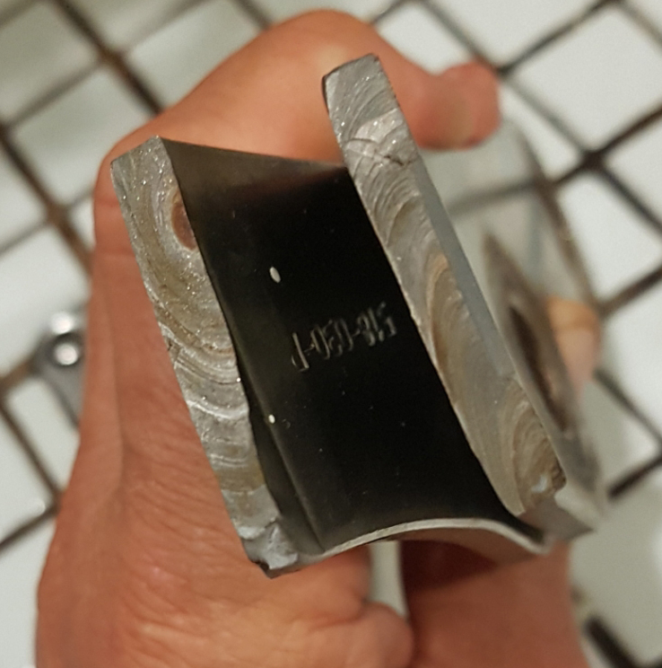
Your Analysis for Failure Mode 1:
- Identify Potential Cause(s): Brainstorm at least two potential design-related causes for a crack to form at the bend. (Hint: Think about material selection, geometry, and design rules).
- Assign Risk Ratings (S, O, D):
- Severity (S): Based on the most serious potential effect, what is the S rating? Justify it using the Severity table.
- Occurrence (O): Choose one of your causes. How likely is it to occur, given this is a new design with HSLA steel? Justify your rating using the Occurrence table.
- Detection (D): What is our current plan to detect this? (e.g., FEA simulation, physical prototype testing). How effective is that method? Assign a D rating and justify it.
- Determine Action Priority (AP): Using your S, O, and D ratings, find the Action Priority (H, M, or L) from the AP table. Is this a top priority for action?
Failure Mode 2: Hole Misalignment Due to Springback
- Function: Provide an accurate mounting interface for assembly.
- Failure Mode: Mounting hole pattern is dimensionally incorrect (e.g., off-position).
- Potential Effect(s) of Failure:
- Inability to install fasteners during vehicle assembly on the line (line stoppage).
- Forced assembly induces stress into the bracket or mating parts, potentially leading to premature failure.
- Loose fit results in BSR issues.
Your Analysis for Failure Mode 2:
- Identify Potential Cause(s): Brainstorm at least two potential design-related causes for the hole pattern to be incorrect due to springback. (Hint: Think about material properties and part geometry).
- Assign Risk Ratings (S, O, D):
- Severity (S): What is the S rating for an assembly line stoppage? Justify it.
- Occurrence (O): How likely is your chosen cause, considering the known challenges of springback with HSS? Justify it.
- Detection (D): How would we detect this? (e.g., CMM layout on initial parts). How effective is this at preventing a bad part from reaching the assembly plant? Assign and justify your D rating.
- Determine Action Priority (AP): Using your S, O, and D ratings, find the Action Priority (H, M, or L). Where does this rank in your priorities?
Take your time to think through this process. A well-executed DFMEA is one of the most valuable activities a design engineer can lead. It forces a deep, critical examination of the design and its interaction with the physical world.
Conclusion
Today we have formalized our risk assessment by applying the DFMEA methodology. This exercise moved us from a general DFM review to a structured, data-driven prioritization of potential design failures.
Key takeaways from this lesson are:
- The DFMEA is built on the failure chain: analyzing how a design Cause leads to a Failure Mode, which results in a Failure Effect.
- Risk is quantified using Severity (S), Occurrence (O), and Detection (D) ratings, which are rooted in established industry criteria.
- Prioritization is now driven by Action Priority (AP), ensuring that high-severity issues receive attention regardless of their RPN score.
- The failure modes identified here are not just theoretical; they are real-world risks directly tied to our material choice (HSLA steel) and manufacturing process (stamping).
In our next lesson, we will use this analysis to define a robust GD&T scheme for the bracket. The features and functions associated with our high-priority failure modes are precisely the ones that will require the most stringent geometric controls to ensure our design intent is met.
Can't find a good explanation? Sign up and we'll make it for you
Sign up