
Welcome back. In our last session, we translated the "golden rules" of sheet metal design into specific dimensions for our bracket, calculating the bend radius, flange length, and relief cuts. This established a baseline for a manufacturable design.
Today, we will elevate our perspective from applying individual rules to conducting a holistic Design for Manufacturing (DFM) review. Our goal is to scrutinize the bracket design for stamping feasibility, specifically identifying and proposing mitigations for the two most prevalent risks in sheet metal forming: springback and tearing. This is a critical step where a design engineer anticipates and solves manufacturing problems before they ever reach the factory floor.
1. The Core Risks: Springback and Tearing
A successful DFM review is built on a solid understanding of what can go wrong during manufacturing. For stamping, especially with High-Strength Steels (HSS), two phenomena dominate.
Springback: The Shape-Shifting Problem
Springback is the elastic recovery of the sheet metal after the stamping pressure is removed. The material "springs back" slightly towards its original flat shape.
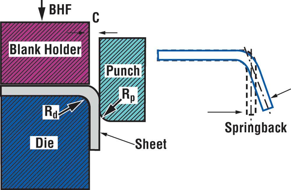
With higher-strength materials like our HSLA steel, this effect is more pronounced and can lead to significant dimensional inaccuracies, such as:
- Angular Change: Flanges do not meet their intended angle (e.g., an 88° angle instead of 90°).
- Sidewall Curl: The walls of a channel or U-section bow inwards or outwards.
- Twist: The entire part distorts along its length.
Correcting these issues on the production line is expensive and time-consuming. Our job is to anticipate and design for it.
Tearing: The Material Failure Problem
Tearing, also known as splitting or fracturing, occurs when the material is stretched beyond its formability limit. This is a catastrophic failure that results in a scrapped part. Key causes include:
- Stress Concentrations: Sharp internal corners where material is forced to flow in multiple directions are common failure points. This is precisely why we use bend reliefs.
- Insufficient Bend Radius: Bending the material too sharply for its ductility causes cracking on the outer surface.
- Excessive Material Stretching: Complex geometries or deep-drawn features can thin the material to its breaking point.

2. Performing a Stamping DFM Review
A DFM review is a systematic check against established best practices. We've already covered some basics, but a thorough review for stamping feasibility goes deeper.
Let's watch a video that critiques a sheet metal design, highlighting common flaws. This will help you develop an eye for potential issues.
Only Real Mechanical Engineers Can Spot These Design Mistakes | Sheet Metal
The video "Only Real Mechanical Engineers Can Spot These Design Mistakes" by Engineering Gone Wild provides an excellent framework for a DFM review.
Pay close attention to the following sections as the presenter identifies and corrects design flaws: Bend Radius: Note the discussion on how bend radius for harder materials should be a multiple of the thickness. This reinforces our 1.5T decision for HSS. Grain Direction: This is a more advanced concept. The key takeaway is that bending across the material's grain direction is preferred to prevent cracking. Hole Size and Locations: This section introduces critical rules for placing holes relative to bends and edges to prevent distortion. Bend Relief: A great recap on why and how to apply bend reliefs to prevent tearing.
The video gives us a solid foundation. Now, let's look at the authoritative industry guides to understand how to specifically address the high-risk issue of springback in HSS parts.
Correcting Springback - AHSS Guidelines
This article from AHSS Insights is a definitive guide to understanding and correcting springback. It details both part design and die process solutions.
As you read, focus on these three core strategies: Changing the Elastic Strain Distribution (Post-Stretch): Read the overview of this section. The key concept is that by applying a 2% tensile stretch after the initial bend, you can convert the damaging compressive/tensile stress gradient into a uniform tensile stress, which dramatically reduces springback. Pay attention to the diagrams in Figures 1 and 2. Changing the Elastic Strain Distribution (Over-Forming): Review this section. This is a common die-based solution where the part is intentionally bent to a sharper angle (e.g., 88°) so it springs back to the desired 90°. Note how part design (Figure 13) can enable or prevent the ability to over-bend. Locking in the Elastic Strains: This is a powerful part-based strategy. Read the section and look at Figures 18, 19, and 21. Features like darts, beads, and step flanges act as geometric stiffeners that physically prevent the part from springing back.
This knowledge gives you, the design engineer, two types of tools:
- Part-Integrated Solutions: Designing features like stiffening darts directly into your CAD model.
- Process-Aware Design: Designing the part in a way that allows the die makers to implement solutions like over-bending.
3. Your Task: Conduct the DFM Review on the Bracket
Imagine you are leading the design review for our 2.0 mm HSLA steel bracket. Your task is to analyze the design for stamping feasibility, focusing on the risks of springback and tearing.
Use the principles we've just discussed to answer the following questions. There are no perfect answers; the goal is to demonstrate your thought process as a senior engineer.
-
Springback Risk Assessment:
- Looking at the overall geometry of our bracket, which features do you believe are most susceptible to springback? Consider long, unsupported flanges or large-radius bends. Why did you choose these areas?
- Propose one part-integrated design change to improve dimensional stability. Would you add a stiffening dart, a step-flange, or another feature? Describe or sketch where you would place it and explain your rationale. In CATIA, this could be modeled with the
Stiffening RiborEmbossfeature.
-
Tearing and Distortion Risk Assessment:
- Review the placement of the mounting holes on the bracket. Based on the DFM rules (e.g., distance from bend > 2.5T + R), are any holes at risk of being distorted during stamping? If so, what is your recommended action? (e.g., move the hole, change the flange length).
- Are there any "sharp" internal corners in the design where two bend lines might converge without adequate relief? If so, identify this as a critical tearing risk that must be addressed with a proper bend relief cut.
-
Process Recommendation:
- You are speaking with the die process engineer. Based on your springback assessment, what compensation strategy would you recommend they plan for? Would you suggest they prepare for over-bending the flanges in the die? Or would you recommend a more advanced post-stretch process using stake beads? Justify your choice based on the part's complexity and material.
Take your time to think through these questions. This exercise simulates a real-world engineering review where you must defend your design choices and proactively solve manufacturing challenges.
Conclusion
Today, you have transitioned from a designer who applies rules to a lead engineer who assesses risk. We've conducted a high-level DFM review focused on stamping feasibility.
The key takeaways are:
- DFM is a proactive risk analysis. For stamping, the primary risks are dimensional failures from springback and material failures from tearing.
- Springback can be controlled. We can use part-integrated features like stiffening darts or design the part to enable die processes like over-bending and post-stretching.
- Tearing is prevented by managing stress. This is achieved with appropriate bend radii, generous bend reliefs, and following placement rules for features like holes.
In our next lesson, we will formalize this risk analysis by creating a Design Failure Mode and Effects Analysis (DFMEA) for the bracket. The potential issues we've identified today—springback causing dimensional error, tearing at a corner, hole distortion—will become the "potential failure modes" in our DFMEA.
Can't find a good explanation? Sign up and we'll make it for you
Sign up