
Hello! Welcome back to our course.
In the past few lessons, we've focused on how external forces create internal stresses within a material—specifically normal stress, shear stress, and bearing stress. Today, we'll connect stress back to a concept from an earlier lesson: strain. We will explore how axial stress causes a member to physically change its length. This change, known as deformation or elongation, is a critical design consideration. An aircraft wing strut must not only be strong enough to not break, but also stiff enough to not stretch or shrink excessively under load.
Our learning outcome for this lesson is to analyze deformation and elongation in bars under axial loads, including statically indeterminate cases. We will start with the fundamental formula for calculating elongation in simple cases and then move on to more complex situations where the basic equations of statics are not enough to solve the problem.
1. Axial Elongation: The "PL/AE" Formula
When an axial force is applied to a bar, it causes a normal stress . This stress, in turn, causes a normal strain , which is the change in length per unit length. Recalling Hooke's Law (), we can combine these simple relationships into one powerful formula that directly calculates the total change in length, .
Where:
- (delta) is the total change in length (elongation or contraction).
- is the internal axial force in the member.
- is the original length of the member.
- is the cross-sectional area.
- is the Young's Modulus of the material.
This formula is a cornerstone of mechanics of materials. Let's watch a video that introduces this formula and shows how to apply it.
Mechanics of Materials: Lesson 17 - Axial Elongation Due to Axial Load Example
This video from Jeff Hanson provides a clear, practical introduction to the axial elongation formula and works through a typical example involving a bar with multiple loads.
Please watch from the beginning to 11:21. Pay close attention to: The explanation of each term in the formula \delta = PL/AE (often called the 'play' equation). The method used to find the internal force 'P' in each distinct segment of the bar. How the total change in length is the sum of the changes in each segment, being careful with signs (tension causes positive elongation, compression causes negative).
Principle of Superposition
As demonstrated in the video, if a bar consists of multiple segments with different loads, cross-sections, or materials, we can find the total deformation by calculating the deformation of each segment individually and adding them up. This is an application of the Principle of Superposition.
The total deformation is the algebraic sum of the deformations of the individual segments:
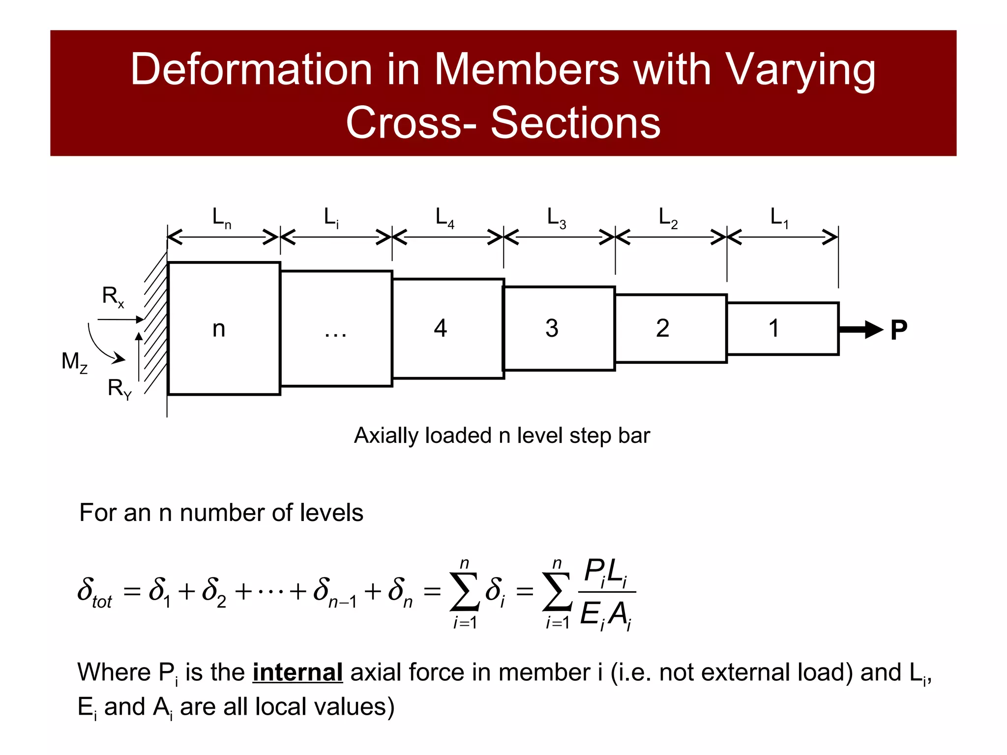
A critical first step is always to find the internal force in each segment. This is done using the method of sections, as shown in the video. You make an imaginary "cut" in the segment you're interested in and use the equations of static equilibrium () on the free-body diagram to find the internal force. Remember the sign convention:
- Tension (pulling apart) is positive (+).
- Compression (pushing together) is negative (-).
2. Statically Indeterminate Problems
So far, we've looked at problems where you could find all the reaction forces using only the equations of static equilibrium (). These are called statically determinate problems.
Now, let's consider a bar that is fixed at both ends and has a load applied somewhere in the middle.

In the bottom case, we have two unknown reaction forces ( and ) but only one relevant equilibrium equation (). We have more unknowns than equations. This is a statically indeterminate problem.
How do we solve it? We need an additional equation. This equation comes from the geometry of the deformation. It's called a compatibility equation.
STATICALLY INDETERMINATE Structures in 10 Minutes! - Axial Loading
This video from Less Boring Lectures explains what statically indeterminate problems are and demonstrates a direct method for solving them.
Watch the sections from 00:00-02:26 and 04:15-06:21. The first part explains why these problems are indeterminate. The second part shows a direct and efficient method to solve them by combining equilibrium and deformation equations. Focus on the core idea of using a 'compatibility equation'.
The Solution Strategy
As the video and supporting text below explain, solving statically indeterminate axial load problems involves a clear, four-step process.
Summary of axially-loaded members
This document from Purdue University provides an excellent, structured summary of the problem-solving method for axially loaded members. It formalizes the steps we've just seen.
Please read the following sections: Section (b) 'Problem solving method': This outlines the four key steps. Section (e) 'Compatibility equations': Focus on the logic for 'Collinear elements', especially the case where a bar is fixed at both ends (e.g., u_E=0). This provides the geometric constraint we need. Section (f) 'Solving determinate and indeterminate problems': This confirms that for indeterminate problems, you must solve equilibrium and compatibility equations simultaneously.
Let's summarize the four-step method for solving these problems:
-
Equilibrium: Draw a free-body diagram of the entire structure and write down the relevant static equilibrium equations. You will have more unknowns than equations.
- Example:
-
Compatibility: Write an equation that describes the geometric constraints on the deformation.
- For a bar fixed at both ends, the total change in length must be zero.
- Example: , where AC is the segment from the left wall to the load, and CB is the segment from the load to the right wall.
-
Force-Displacement Relationship: Express the deformations in the compatibility equation in terms of the unknown forces using the elongation formula, . Be careful to correctly identify the internal force in each segment in terms of the unknown reactions.
- Example: The internal force in segment AC is , and the internal force in segment CB is (or ). So the compatibility equation becomes:
-
Solve: You now have a system of two equations (one from equilibrium, one from compatibility) and two unknowns ( and ). Solve them simultaneously to find the reaction forces. Once the reactions are known, you can find the stresses and deformations in each segment.
Test your understanding!
A steel rod ( GPa) with a cross-sectional area of is placed between two fixed walls. The rod is composed of two segments: AC (length 0.5 m) and CB (length 1.0 m). A force of kN is applied at point C.
- Write the equilibrium equation relating the reaction forces and .
- Write the compatibility equation based on the total deformation.
- Use these two equations to find the reaction force .
Show answer
-
Equilibrium Equation: From a free-body diagram of the rod, assuming both reactions push back on the rod (compression):
. Let's redefine the reactions to be positive in tension, pointing away from the rod. So, . Let's use the convention from the videos and assume reaction forces are positive when pointing right. So, . (Any consistent convention works). Let's stick with at the left wall and at the right wall, both pointing left (compressive reactions). So . -
Compatibility Equation: Since the rod is fixed at both ends, the total change in length must be zero.
. -
Solve for :
- The internal force in segment AC is (compression).
- The internal force in segment CB is (compression, if we look from the right wall), which is also .
- Substitute into the compatibility equation:
Since and are constant, they cancel out:
- And .
This method can also be extended to problems involving thermal expansion, where a change in temperature adds another term to the deformation equation: . You will see this in future, more advanced problems.
Conclusion
In this lesson, you've learned how to quantify the change in length of components under axial load, a crucial step in ensuring a design is not just strong, but also sufficiently stiff.
Key Takeaways:
- The deformation of an axially loaded member is given by the formula .
- For members with multiple segments, the total deformation is the algebraic sum of the individual segment deformations.
- Statically indeterminate problems have more unknown forces than can be solved by static equilibrium alone.
- To solve them, we introduce a compatibility equation that describes the geometric constraints of the system (e.g., total deformation is zero).
- The solution requires simultaneously solving the equilibrium equations and the compatibility equations.
Next Lesson Preview:
We've now analyzed 1D stress (axially loaded bars) quite thoroughly. However, many components in engineering, especially in aerospace, experience stresses in two directions simultaneously. A classic example is a pressurized aircraft fuselage or a fuel tank. In our next lesson, we will begin our look into 2D stress states by learning how to determine stresses in thin-walled pressure vessels using hoop and longitudinal stress formulas.
Can't find a good explanation? Sign up and we'll make it for you
Sign up