
Hello! Welcome back to our course on Mechanical Engineering fundamentals.
In our last lesson, we explored normal stress () and strain (), which arise from forces acting perpendicular to a surface (pulling or pushing). We saw how the stress-strain curve reveals a material's core properties like stiffness and strength.
Today, we shift our focus to forces that act parallel to a surface. This is crucial for understanding how connections like bolts, rivets, and pins hold structures together. Our learning outcome is to calculate shear stress and strain in materials under direct shear and bearing stress in connections. By the end of this lesson, you'll be able to analyze the stresses in a simple bolted or pinned joint, a fundamental skill for designing anything from aircraft control linkages to structural steel frames.
1. Distinguishing Shear and Bearing Stress
While normal stress involves pulling or pushing on a cross-section, other types of stress are equally important. Let's start by defining two new types: shear stress and bearing stress.
Different types of stress (Lecture and example)
This short video from Mechanics of Materials (Libre) provides a clear and concise introduction to the concepts of shear stress and bearing stress, contrasting them with the normal stress we've already covered.
Watch from the beginning to 02:33. Focus on the key distinction: normal stress comes from a force perpendicular to the area, while shear stress comes from a force parallel to the area. Also, note how bearing stress is defined as a contact pressure between two separate bodies.
To summarize the video's key points:
-
Shear Stress (): This is stress caused by forces acting parallel to the area, creating a "sliding" or "shearing" effect. The average shear stress is calculated as:
where is the shear force and is the area being sheared. -
Bearing Stress (): This is a type of compressive stress that occurs at the contact surface between two separate components, like a bolt pressing against the inside of a hole. It's calculated as:
where is the compressive force and is the bearing area.
2. Shear Stress in Connections: Single vs. Double Shear
Shear stress is the primary mode of failure for fasteners like bolts and pins. Imagine using scissors to cut paper—the two blades slide past each other, shearing the paper in between. A bolt in a joint experiences a similar effect.
A critical concept in analyzing these connections is whether the fastener is in single shear or double shear.
Mechanics of Materials: Lesson 4 - Shear Stress, Single and Double Shear Example
Let's watch a segment from a video by Jeff Hanson that uses a great analogy and clear diagrams to explain single and double shear.
Watch from the beginning to 04:26. Pay attention to the 'scissors' analogy for shear. Most importantly, focus on the visual difference between a single shear pin, which would only need to be 'cut' once to fail, and a double shear pin, which would need to be 'cut' in two places.
As the video explained, the distinction is about how many cross-sections of the pin are resisting the load.
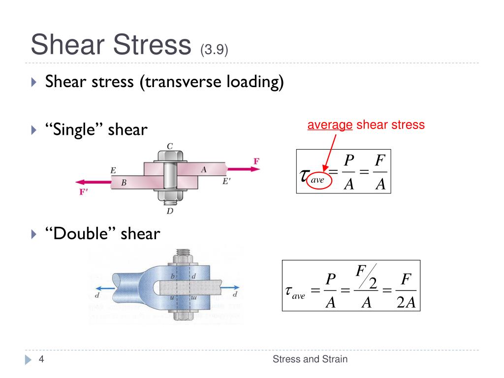
- Single Shear: The load is transferred across a single cross-section of the bolt or pin. The shear area is simply the cross-sectional area of the pin: .
- Double Shear: The load is transferred across two cross-sections. This is common in clevis joints, which are ubiquitous in aerospace for connecting control rods. The total shear area is doubled: .
For a given load and pin diameter, a double shear connection is twice as strong against shear failure because the load is distributed over two planes. This makes it a more efficient design.
3. Bearing Stress: The Crushing Force
Whenever a pin or bolt presses against the material of a hole, it creates bearing stress. If this stress is too high, the hole can be elongated or the material can be crushed, leading to a loose connection and eventual failure.
The key to calculating bearing stress is understanding the area over which it acts. While the contact surface is curved, for engineering calculations, we simplify this by using the projected area.
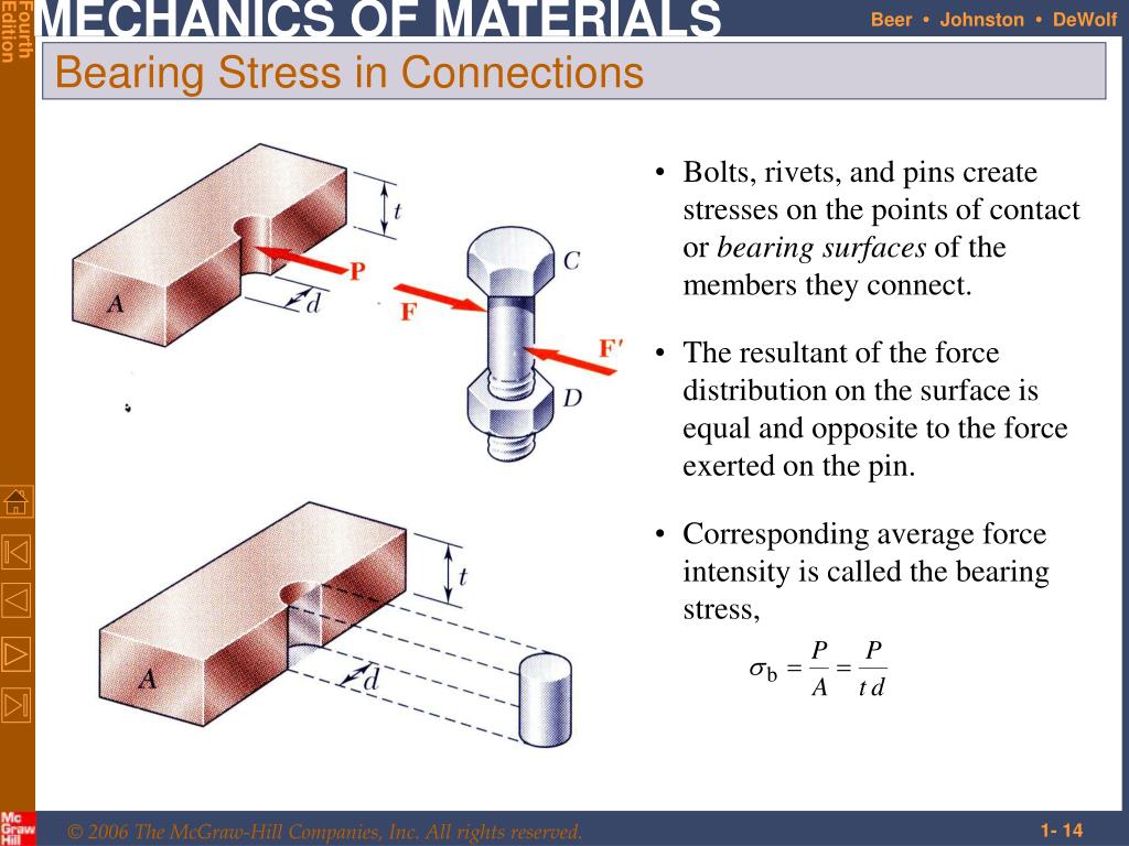
The projected bearing area, , is the rectangle formed by the pin's diameter () and the thickness of the plate ().
This simplification provides the average stress and is a safe and standard practice in engineering design.
Test your understanding!
A simple lap joint is formed by bolting two 8 mm thick plates together with a single 20 mm diameter bolt. A tensile force of 50 kN is applied to the plates.
- Is the bolt in single or double shear?
- Calculate the shear stress () in the bolt.
- Calculate the bearing stress () between the bolt and one of the plates.
Show answer
-
Single Shear: In a simple lap joint, the bolt is only sheared across one plane.
-
Shear Stress Calculation:
- Shear force .
- Shear area .
- .
-
Bearing Stress Calculation:
- Bearing force .
- Plate thickness .
- Bolt diameter .
- Bearing area .
- .
4. Shear Strain
Just as normal stress causes normal strain (elongation), shear stress causes shear strain (). Shear strain is not a change in length, but a change in angle. It measures the distortion of a shape.
Imagine a square element of material. When a shear stress is applied, the square deforms into a rhombus. The change in the corner angle from the original 90 degrees (or radians) is the shear strain, .
This section from a set of course notes provides a good visual and definition for simple shear stress and shear strain.
Please read section '1.15 Simple Shear stress and Shear Strain'. Focus on the diagram showing the rectangular block deforming and understand that shear strain (\phi in the text, commonly denoted by \gamma) is the angle of distortion.
Analogous to Hooke's Law for normal stress (), there is a similar relationship for shear stress within the elastic region:
Here, is the Shear Modulus or Modulus of Rigidity. It's a material property that measures resistance to shear deformation, just as Young's Modulus () measures resistance to tensile deformation.
5. Putting It All Together: A Complete Example
Now let's see how these concepts are applied in a complete problem. This often requires a first step of performing a static analysis to find the forces acting on the connections, which should be a good refresher for you.
Mechanics of Materials: Lesson 4 - Shear Stress, Single and Double Shear Example
This video from Jeff Hanson works through a complete problem from start to finish. It involves finding the forces on two different pin connections using statics, and then calculating the shear stress in each pin—one of which is in double shear and the other in single shear.
Watch from 04:26 to the end (14:08). Follow along with the calculations. Notice how the first part of the problem is pure statics (finding reaction forces), and the second part applies the shear stress formulas we've just learned.
This example highlights a critical part of engineering analysis: you must first determine the forces acting on a component (Statics) before you can determine the internal stresses it will experience (Mechanics of Materials).
Conclusion
Today, we've expanded our toolkit for stress analysis beyond simple tension and compression. You've learned how to identify and calculate the stresses in some of the most common mechanical connections.
Key Takeaways:
- Shear Stress () is caused by forces acting parallel to a surface, and it's calculated as .
- Bearing Stress () is the compressive contact stress between two bodies, calculated using the projected area: .
- Connections can be in single shear (one failure plane) or double shear (two failure planes). Double shear connections are more efficient, as they halve the shear stress for the same load.
- Shear Strain () is the change in angle due to shear stress, related by the Shear Modulus ().
- Analyzing connections often requires a combination of statics to find forces and mechanics of materials to find the resulting stresses.
Next Lesson Preview:
So far, we have analyzed stresses that are assumed to be uniform over a cross-section (axial loads) or in a specific connection (direct shear). However, many structural members, like aircraft wings or floor joists, are subjected to bending. Bending induces internal forces that vary along the length of the member. In our next lesson, we will learn how to construct shear force and bending moment diagrams to map out these internal forces, a critical first step before we can calculate bending stresses.
Can't find a good explanation? Sign up and we'll make it for you
Sign up