
Welcome back. In the previous lesson, you established the evidence chain behind FlyWire: EM imagery is the observation, segmentation is a fallible computational interpretation, proofreading tests that interpretation, and the resulting reconstructions support connectome analysis.
This lesson is deliberately conservative. Before deciding whether a neurite is continuous, and well before attempting a merge or split, you need a repeatable inspection view: the correct location in the EM stack, a readable segmentation overlay, and a 3D mesh that is visible without obscuring the evidence. By the end, you will have a no-edit inspection preset and a way to capture that exact state for later review.
The inspection principle: 2D is evidence; 3D is context
Treat FlyWire as a coordinated multi-view debugger for a 3D dataset.
The 2D EM pane is where you inspect the source evidence. It shows grayscale image sections through the tissue. Here, you look for membrane boundaries and trace whether a process remains continuous as you step through slices.
The segmentation overlay is the model’s current proposed assignment of image voxels to an object. It should be visible enough to compare against the EM, but never so opaque that it replaces the EM evidence.
The 3D view is global context. It helps you see whether the currently selected segmentation has the broad shape you expect: a short fragment, a branching arbor, an implausibly long appendage, or a suspicious neighboring piece. It cannot by itself establish that two profiles in an EM image are the same neurite.
A useful default division of labor is:
| View | Primary question | What it cannot settle alone |
|---|---|---|
| 2D EM image | “What membranes and cellular profiles are present at this location?” | The complete global morphology |
| 2D segmentation overlay | “What does the current reconstruction claim belongs together here?” | Whether that claim is correct |
| 3D mesh | “What is the larger shape and spatial context of the selected object?” | Local continuity across ambiguous image sections |
| Coordinates | “Precisely where is this observation?” | What the structure means biologically |
The annotated interface image below shows this arrangement: an EM section on the left, a 3D view on the right, the coordinate readout along the top, layer tabs near the top of the workspace, and Layer Controls at right.
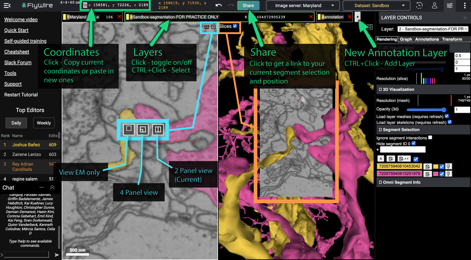
The screenshots in this lesson use an earlier FlyWire interface and a sandbox dataset. Your account may show different layer names or a revised layout, but the concepts—EM imagery, segmentation layer, coordinates, rendering controls, and 3D mesh visibility—remain the same.
Learn the safe navigation controls first
For this lesson, navigation is the only interaction you need. In particular, avoid double-clicking while you are still building muscle memory: FlyWire documents double-click as the command that adds or removes segments. Later, you will use selection and editing intentionally; for now, keep the session observational.
How to Use FlyWire – FlyWire Blog
Read the opening navigation guide from the FlyWire Blog. It establishes the small set of mouse and keyboard interactions needed to move through the EM stack and manipulate the 3D object without making a reconstruction edit.
In the opening interface instructions, focus on the subsection “2D (EM) or 3D Navigation” and the following “Navigating 3D space” and “Navigating 2D (EM) space” subsections. Read the control list, noting the distinction between scrolling in the 2D pane to move through slices and click-dragging in the 3D pane to rotate the mesh.
Use the controls according to the pane under your cursor:
| Intent | Interaction | Inspection use |
|---|---|---|
| Pan within a 2D EM section | Click and drag in the 2D pane | Center a profile, membrane boundary, or suspected join |
| Step through the image stack | Scroll in the 2D pane | Check continuity across adjacent sections |
| Zoom | Hold Ctrl and scroll | Move between local membrane detail and a wider field of view |
| Rotate the 3D model | Click and drag in the 3D pane | Check the selected object’s morphology from another angle |
| Jump to a point of interest | Right-click the relevant area | Recenter the views on a local feature |
| Undo a UI action | Ctrl+Z | Recover from an accidental navigation or selection action where supported |
Two cautions matter:
- Use ordinary scroll only when the cursor is over the 2D pane. In inspection, stepping slice by slice is not the same thing as zooming.
- Do not rely on Undo as protection for future edits. FlyWire’s guide explicitly warns that Undo does not reverse reconstruction merges or splits. The safest workflow is to establish evidence before an edit, rather than treating Undo as a recovery plan.
For this lesson, consider a successful navigation action one that changes only your view, not the dataset.
Build a no-edit inspection view
A good inspection configuration makes disagreements visible. If the colored overlay is completely opaque, you cannot see whether it respects EM membranes. If it is too faint or the imagery is too coarse, you cannot tell what the segmentation is claiming. If the 3D mesh is hidden, you lose morphology; if you rely only on the mesh, you lose the image evidence.
1. Locate the coordinate readout
At the top of the FlyWire workspace is a coordinate display with three values, conventionally , , and . These are positions in the dataset volume, not screen pixels.
Use coordinates as the address of an observation:
- and locate a point within the current image plane.
- identifies the position through the stack of image sections.
- The three values together identify one location in the 3D EM volume.
Clicking the coordinate field lets you copy the current location and, when you later receive a location from a task or collaborator, paste coordinates to navigate there. The most important habit is to record all three values together. A note such as “interesting branch at ” is not reproducible without its and location.
For a first calibration, pan to any distinctive structure and step through several slices. Watch the coordinate display as you do so. The image should change mainly as the stack position changes, while the coordinate triple gives you a stable address to return to.
2. Make sure the essential layers are visible
FlyWire uses layers to display different kinds of information. During ordinary proofreading, the segmentation layer is the one you will work with most often; in the example interface it is Layer 2.
At the top of the interface:
- Identify the EM image layer and leave it visible.
- Identify the segmentation layer and leave it visible.
- Leave annotations visible only if they are relevant to the inspection; otherwise, reduce visual clutter.
- Select the segmentation layer with Ctrl+click or right-click if Layer Controls are not already open.
Read the FlyWire 101 discussion of layers, Layer Controls, rendering, and sharing. This is the reference for opening the controls associated with the segmentation layer and for saving a reproducible inspection state.
In the opening layers discussion, read from layer visibility through Layer Controls. Then read the “Sharing” subsection, from the Share-button explanation. Focus on the fact that controls belong to the selected layer and that a Share link preserves both location and selection state.
This layer model is similar to compositing in a graphics application: visibility answers whether a data source is drawn at all, while rendering parameters determine how it is drawn. Do not confuse “layer hidden” with “data absent.” Hiding a segmentation layer only changes your view.
3. Tune the 2D overlay for comparison, not decoration
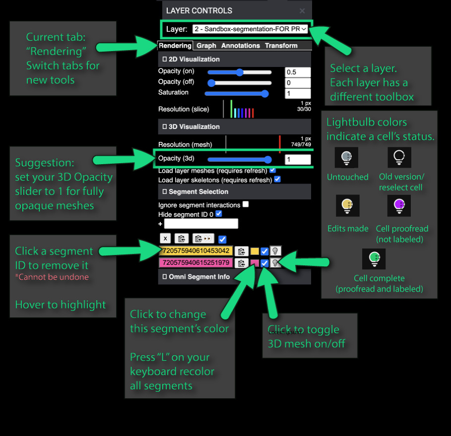
With the segmentation layer selected, open Layer Controls, then the Rendering tab. The exact labeling can vary, but look for controls corresponding to:
- 2D Visualization
- segmentation opacity
- saturation
- resolution (slice)
The practical objective is a balanced overlay:
- Turn on 2D Visualization.
- Keep the segmentation overlay visibly colored, but partly transparent.
- Adjust opacity until you can see both the colored claim and the underlying grayscale membrane evidence at the same time.
- Use higher slice resolution when examining a small ambiguous boundary; use a less demanding setting when orienting over a larger area or if rendering becomes sluggish.
Avoid memorizing a universal opacity number. A thick, dark EM boundary may tolerate a stronger overlay; a faint or crowded region needs a more transparent one. The correct setting is the one that lets you answer both questions simultaneously:
Where does the segmentation say this object is?
What does the EM image actually support?
The Rendering panel also may expose separate opacity states labeled “on” and “off.” Treat these as display states for the segmentation, not as claims about the biology or proofreading quality of the neurite. What matters in this lesson is that the colored overlay remains interpretable against the EM imagery.
4. Enable a readable 3D mesh
In the same Rendering tab, find the 3D Visualization section.
For a standard inspection setup:
- Enable 3D visualization.
- Enable loading of the layer’s meshes if that option is shown. Some FlyWire configurations note that a refresh may be required.
- Set 3D opacity near full opacity so the mesh is visually solid.
- Keep the 3D view large enough to rotate and inspect, but do not let it replace the 2D pane as the main evidence view.
A fully opaque mesh is appropriate because it affects the 3D rendering pane, not the EM evidence underneath the 2D overlay. In the 3D pane, rotate the mesh once or twice. Your immediate goal is only to confirm that it is loaded, visible, and responsive.
A mesh can contain an apparent discontinuity because the current segmentation is a fragment; conversely, it can look smoothly continuous while the EM evidence reveals an incorrect local connection. This is why the configuration keeps both views open.
A repeatable inspection preset
Use the following compact routine whenever you open a new FlyWire location. It should take less than two minutes once familiar.
No-edit inspection checklist
- Coordinate: Record or confirm the full location.
- EM: The grayscale imagery is visible and sufficiently zoomed to see boundaries relevant to the question.
- Segmentation overlay: The segmentation layer is visible in 2D and transparent enough that EM detail remains legible.
- 3D mesh: The selected object is visible in 3D, with mesh opacity high enough to assess its overall form.
- Layer selection: Layer Controls belong to the segmentation layer, rather than an annotation or image layer.
- No edit commands: You have used pan, slice scrolling, zoom, rotation, and right-click navigation only; no double-clicking and no merge/split tools.
- Snapshot: Once the view is informative, use Share to create a link that captures the coordinate, selected segments, and displayed state.
The final item is more than convenience. A Share link is an inspectable reference for a future discussion: it lets another person begin from the same spatial location and see the same selected segment state. It is the visual counterpart to recording parameters in a notebook.
A useful naming convention in your personal notes is:
case: exploratory-001
coordinate: x, y, z
view: EM + transparent 2D segmentation + visible 3D mesh
status: inspection only; no edit made
share link: [saved link]
This is not yet an audit log of an edit—that comes in the next module—but it begins the habit of separating what you observed from what you changed.
Troubleshooting without touching the reconstruction
Most first-session problems are configuration problems, not biological puzzles.
| Symptom | Likely cause | Safe response |
|---|---|---|
| Only grayscale EM is visible | Segmentation layer is hidden or 2D visualization is off | Confirm layer visibility, select the segmentation layer, and enable 2D visualization |
| Colored overlay dominates the image | Overlay opacity is too high | Reduce 2D opacity until membrane boundaries are readable |
| Segmentation is difficult to see | Overlay opacity is too low, or it is outside the field of view | Increase opacity modestly; pan or jump to the intended coordinate |
| 3D pane is empty | Mesh rendering or mesh loading is disabled, or no suitable segment is displayed | Check 3D Visualization and mesh-loading controls; refresh only if the interface indicates it is required |
| Layer Controls are missing | No layer is selected for configuration | Ctrl+click or right-click the segmentation layer |
| You have lost the location | The view was moved without a recorded coordinate | Return using a saved Share link or re-enter the coordinate triple if you recorded it |
Notice what is absent from every response: merging, splitting, or guessing. A blank mesh, an invisible overlay, or a confusing coordinate is a reason to correct the visualization state, not a reason to alter a reconstruction.
Takeaways and next step
You now have the operational foundation for safe FlyWire inspection:
- The 2D EM view is the primary evidence layer.
- A partially transparent segmentation overlay lets you test the model’s claim against image structure.
- The 3D mesh supplies morphology and broader context, but does not prove local continuity.
- A complete coordinate identifies an observation reproducibly.
- Selecting the segmentation layer exposes its Layer Controls, including 2D and 3D rendering settings.
- The Share button captures a useful snapshot of coordinates, selected segments, and view state.
- Navigation and rendering configuration are not reconstruction edits; nevertheless, avoiding double-clicks while learning keeps the session safely observational.
Next, you will use this setup to navigate to a specified location and trace the same neurite through adjacent EM sections. The central skill will shift from configuring the evidence view to following continuity through the image stack.
Can't find a good explanation? Sign up and we'll make it for you
Sign up