
Hello. In the previous lesson, you created a hazard register and a pre-power checklist for the arm, gripper, mobile base, and battery system. The central safety decision was to reduce risk before energizing hardware: clear the operating envelope, use an accessible disconnect, verify wiring unpowered, and begin with limited motion and energy.
This lesson turns that checklist into an engineering method: a staged power-up procedure. Rather than connecting the entire robot and hoping it works, you will prove one small subsystem at a time, record a pass/fail decision, and only then add the next interface. This makes faults much easier to locate and prevents one wiring or software mistake from damaging several parts at once.
By the end, you will have a reusable power-up procedure for both the robotic arm and the differential-drive base, plus a test-card format for your build log.
The purpose of staged bring-up
A completed mobile manipulator combines several systems that can fail independently:
- battery, fuse, switch, connectors, and voltage regulators;
- Raspberry Pi and microcontroller;
- sensors and communications;
- motor drivers and servo power distribution;
- arm joints, gripper, wheel motors, and encoders;
- mechanical structure and moving cables.
If all of these are connected for the first power-up, a fault presents as a confusing symptom: perhaps the Pi resets when a wheel starts, a servo twitches at boot, a motor driver overheats, or a joint moves in the wrong direction. You cannot yet tell whether the cause is power, wiring, software, mechanics, or an interaction between them.
A staged procedure controls two variables:
- Scope: only one new subsystem or interface is added at a time.
- Energy: begin with no power, then logic-level power, then a single low-risk actuator test, before full mechanical operation.
The important idea is not “always use a low voltage.” Many electronics need their specified voltage to operate safely and correctly. Instead, use the correct voltage while limiting the possible energy, connected hardware, motion, and duration of the test.
The Hubble Network Community hardware bring-up checklist provides a useful model: inspect first, validate power rails, establish that the controller can communicate and execute a minimal program, then validate additional interfaces.
Hardware Bring-Up Checklist: What to Test Before Writing Firmware – Hubble Network Community
Read this concise Hubble Network Community guide as a model for treating a successful power-up as a sequence of evidence, not merely an illuminated LED.
In Step 1, “Visual Inspection — Look Before You Power,” read from the physical inspection. Then read Step 2, “Power Rail Validation — The Foundation of Everything,” especially rail validation. Skim Step 4, “The Blink Test,” and the final “Printable Hardware Bringup Checklist.” Adapt the logic of the checklist to your robot rather than copying its board-specific details.
A staged power-up has a strict rule:
A failed stage stops the procedure. Disconnect power, document what happened, and diagnose that stage before adding anything else.
Continuing after a failure usually converts one identifiable problem into several new ones.
Your power-up ladder
For this course, use the following seven-stage ladder. Each stage has a specific goal, limited configuration, expected observation, and pass criterion.
| Stage | What is connected | What you are proving | Typical pass criterion |
|---|---|---|---|
| 0. Test planning | No electrical connections required | You know the intended wiring, expected values, hazards, and stop method. | Test card completed; workspace and emergency disconnect ready. |
| 1. Unpowered inspection | Robot unpowered; battery and USB disconnected | Wiring, polarity, mechanical restraint, and obvious shorts are checked before energy enters the system. | Visual inspection and targeted continuity checks pass. |
| 2. Power source and rails | Supply, fuse/disconnect, regulator, or one board only | Correct voltage reaches the intended rail without excessive current draw. | Measured voltage is within the component’s stated allowable range. |
| 3. Controller only | Microcontroller or Pi, with motors and servos disconnected | The controller boots, firmware uploads, and a harmless output works. | Serial connection, status LED, or blink program works consistently. |
| 4. Sensors and signals | Controller plus one sensor, switch, or communication link | Inputs and data paths are wired and interpreted correctly. | Values change plausibly when the physical input changes. |
| 5. Driver, no mechanical load | Controller plus one motor driver or one servo test setup | Command signals and driver enable behavior are correct before a mechanism is attached. | Explicit enable is required; zero command produces no motion. |
| 6. One actuator | One driver/servo plus one supported or isolated actuator | Direction, speed, current behavior, and stop action are safe. | Low-speed command gives the expected direction and reliable stop. |
| 7. Incremental integration | Add one verified subsystem/interface at a time | The new connection does not destabilize already-passing systems. | Previous pass criteria still hold after the addition. |
A “subsystem” should be small enough that it can fail in a bounded, understandable way. For example, do not define “the mobile base” as a first subsystem. Define:
- microcontroller and USB serial connection;
- left motor driver channel with no wheel fitted;
- left encoder;
- right motor driver channel;
- right encoder;
- obstacle sensor;
- both motors on raised wheels;
- floor motion at low speed.
Likewise for the arm, test a shoulder servo or motorized joint individually before testing the assembled arm. A servo attached to a long link is no longer a simple electrical test; it is an electrical, mechanical, and motion test at once.
Stage 0: write a test card before touching power
For every new subsystem, create a short test card in your build log. It forces you to decide what “working” means before you see a result.
Use this format:
| Field | Example: one mobile-base motor channel |
|---|---|
| Test ID and date | T-MB-01, date |
| Subsystem under test | Left DC gearmotor, driver channel A, and microcontroller PWM output |
| Interfaces involved | P-02 actuator rail, S-01 PWM/direction, M-03 wheel mount |
| Configuration | One motor only; wheel removed or chassis raised; encoder disconnected for this first test |
| Expected supply voltage | The voltage permitted by the motor-driver and motor documentation |
| Expected behavior | At zero command, motor remains stopped. A small forward command rotates the output shaft forward. Stop command halts it. |
| Initial limits | Low duty cycle, short run time, no payload, accessible disconnect |
| Measurement plan | Measure actuator rail before command; observe supply current; verify direction visually |
| Stop conditions | Unexpected motion, heat, smell, unusual sound, supply current limit, voltage collapse, loose wiring |
| Pass criterion | Repeats forward, stop, and reverse tests without exceeding limits |
| Result and next action | Pass/fail, measured values, photographs if useful, what may be connected next |
For a first arm-servo test, the safe configuration differs:
- secure the servo in a mount or vise designed not to crush it;
- leave the arm link and payload disconnected where practical;
- keep the horn’s sweep clear of fingers and tools;
- use the servo’s specified supply range;
- make the controller start with a disabled or neutral command;
- perform only short, low-speed movements initially.
For a wheel motor, elevate the driven wheels or test the motor with the wheel removed. A mobile chassis that can roll off a bench is not a controlled electrical test.
Stage 1: inspect and test while unpowered
Before a continuity or resistance test, remove the battery, unplug USB, switch off bench supplies, and ensure no other power path remains. A Raspberry Pi can sometimes be powered unintentionally through USB or connected peripherals, so check every possible source.
Start with visual inspection:
- Compare every wire to the current wiring diagram or interface table.
- Confirm connector polarity, particularly battery, regulator input, motor-driver supply, and servo connectors.
- Check that no bare conductor can contact a neighboring terminal.
- Inspect for loose strands in screw terminals, solder bridges, crushed insulation, and poor strain relief.
- Confirm the correct fuse is installed where the battery positive lead enters the system.
- Verify the arm is supported and the base cannot move.
- Confirm motor-driver enables are disabled or disconnected until that stage is reached.
Then use continuity only for questions you can interpret. Good questions include:
- Is the battery positive lead continuous from the connector to the input side of the fuse?
- Is the fuse’s output continuous to the intended power-distribution terminal?
- Does each ground connection reach the designated common ground point?
- Does a signal wire actually reach its intended controller pin?
- Is the motor cable continuous from connector to motor terminals?
The most important negative check is between the positive and negative rails. With the battery disconnected, test from the protected positive rail to ground. You generally do not want an immediate, stable continuity beep that indicates a direct short. But interpret this carefully: capacitors may cause a brief beep, and motor drivers or other electronics can present a low resistance to a basic meter. A non-beep does not prove the whole circuit is perfect; it merely catches obvious faults before power is applied.
Use Adafruit’s multimeter guide to refresh the exact distinction between unpowered continuity testing, powered voltage testing, and series current measurement. These distinctions prevent common first-power-up mistakes.
Read the “Continuity” section from continuity basics, then pay close attention to the “Remember!” warning that testing must be unpowered, from the unpowered rule. In the “Voltage” section, read the reference probe method. Finally, in “Current,” read how current is measured. Do not try current measurement on the completed robot yet; the goal here is to understand the meter connection required.
Two meter rules are non-negotiable:
- Continuity and resistance measurements are made only on an unpowered circuit.
- Current is measured in series, never by touching the probes across a battery or power rail. Doing that with the lead in the current socket can create a near-short through the meter.
After any current measurement, move the red probe back to the normal voltage/resistance socket. This small habit prevents accidental shorts during later voltage checks.
Stage 2: energize only the power source and logic rail
The first powered test should involve the fewest possible components. For a robot, that normally means no motors, no servos, and no mechanical load.
A bench power supply is useful because it allows you to set the output voltage and place a ceiling on current. A current limit is not a replacement for a fuse or a properly designed power system, but it can prevent a small wiring error from becoming a destroyed board during development.
Benchtop Power Supplies - Electronics with Becky Stern | DigiKey
Watch “Benchtop Power Supplies” from DigiKey’s Electronics with Becky Stern for the practical meaning of constant-voltage and constant-current operation, and for a careful setup sequence.
Watch supply basics to identify the voltage, current, CV, and CC controls. Then watch safe setup, focusing on setting the current limit before energizing an unverified circuit and checking polarity. Apply the concept only with a supply that you understand and that is rated for the task; follow its manual for its exact control sequence.
For a regulated logic subsystem, such as a microcontroller board, sensor hub, or Raspberry Pi power rail:
- Disconnect actuator power branches. Unplug the motor-driver motor supply, servo rail, or individual actuator connectors. Retain only the electronics needed for the test.
- Set the supply to the documented nominal voltage. Do not guess. A nominal 5 V controller rail needs a regulated 5 V source, not an arbitrary lower test voltage.
- Set a conservative current limit based on the board’s expected consumption and documentation. It must allow normal startup but be well below a level that could overheat wiring or components. If the supply immediately enters constant-current mode, switch it off and investigate.
- Turn on output and observe from a distance. Check for unexpected heat, odor, sound, smoke, or a supply reading inconsistent with the expected idle current.
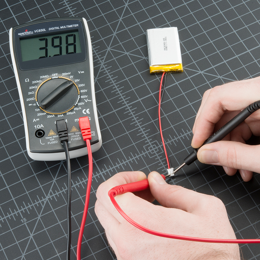
- Measure the rail with your multimeter. Place black probe on the documented ground reference and red probe on the named rail, such as 5 V or 3.3 V.
- Record voltage and current. The value matters less than whether it is within the device’s permitted range and stable.
At this point, the test is not “does the robot move?” It is simply: Does this rail exist at the correct voltage without an obvious fault?
If you are using USB to power a microcontroller during this stage, do not simultaneously connect another 5 V source to that same board unless its documentation explicitly supports that arrangement. Unintended power backfeeding between a Pi, USB, regulator, and controller board is a frequent prototype problem.
Stage 3 and 4: prove controller behavior before actuator power
Once the logic rail passes, validate the controller with a harmless program. For a microcontroller, this might be:
- upload a blink program;
- print a startup message over serial;
- toggle a spare LED;
- report the state of one pushbutton or limit switch.
For a Raspberry Pi, the equivalent could be confirming it boots, that a small script starts, and that it can exchange a known message with the microcontroller. Keep motor drivers disabled and actuators disconnected.
This stage tests several things at once, but at very low energy: the controller boots, your firmware deploys, your pin mapping is plausible, and a basic I/O path works. It also establishes a diagnostic channel before you need it.
Next, attach one sensor or one signal interface. Examples include:
- a limit switch;
- an ultrasonic or distance sensor;
- a wheel encoder channel;
- an I2C sensor;
- a serial link between Pi and microcontroller.
Define a physical action and expected data result. A limit switch should change from open to closed when pressed. A distance sensor should change sensibly as an object moves nearer and farther away. An encoder count should change when you rotate the shaft manually.
At this stage, a passing test does not require perfect calibration. It requires a trustworthy relationship between a physical change and the reported measurement.
Stages 5 and 6: add one driver and one actuator
Motor drivers separate the low-energy command from the higher-energy motor supply. That separation is one reason staged testing is possible: you can validate the controller and command path before allowing the actuator to produce significant motion.
The Ultimate Guide to using Motors in Robotics (including ROS, Raspberry Pi)
Watch selected excerpts from Articulated Robotics’ “The Ultimate Guide to using Motors in Robotics” to see the separation between controller, driver, and motor, and a practical one-motor-first test sequence.
Watch control layers for the distinct roles of the motor, driver, and controller. Then watch one motor setup and individual testing. Notice that the demonstration connects and tests a single motor before expanding the system. Its L298N wiring and software are specific to that demonstration, so use your own driver’s documentation for pin assignments, voltage limits, and current capability.
Before connecting the first actuator, program safe startup behavior:
- On boot, motor PWM is zero and driver-enable outputs are disabled.
- Servo commands start at a documented neutral or safe position.
- Motion requires a deliberate enable action, not merely the controller receiving power.
- A stop command is available and tested before speed is increased.
- The controller does not automatically resume motion after a reset.
Then test only one actuator.
Example: one DC gearmotor
- Secure the motor. Keep its wheel off the ground or elevate the chassis.
- Connect one driver channel and one motor, with no other motor connected.
- Energize the logic rail first and confirm the controller is responsive.
- Energize the motor rail with the disconnect accessible.
- Verify a zero command produces no rotation.
- Apply a small forward command for one or two seconds.
- Send stop. Confirm that the motor stops as expected.
- Apply a small reverse command.
- Disconnect power and inspect connectors, driver, motor, and wiring for unexpected heating.
Example: one arm actuator
- Secure the actuator with the arm link and payload disconnected if feasible.
- Establish a safe physical sweep. The horn, output shaft, or joint must not strike the bench, fixture, cable, or your hand.
- Power the actuator only within its specified voltage range.
- Command a small movement from a known neutral position.
- Confirm the observed direction agrees with the software’s positive direction.
- Test stop behavior, then disconnect power and inspect the mount and cable routing.
For either actuator type, stop immediately if you observe:
- a supply entering current limit unexpectedly;
- supply voltage collapsing;
- rapid heating;
- grinding, binding, or harsh vibration;
- an actuator that moves without a command;
- a direction opposite to the documented command;
- a loose connector or mechanically shifting mount.
Do not solve an unexpected direction by changing wires casually while powered. Disconnect first, make one documented change, repeat the same test, and update the wiring record.
Stage 7: integrate by preserving evidence
Integration should be incremental rather than celebratory. A working controller plus a working motor does not yet prove a working robot. The new interface may introduce electrical noise, mechanical interference, grounding issues, voltage sag, or software timing changes.
A useful integration order for the mobile base is:
- Microcontroller and serial diagnostics.
- One raised motor and driver channel.
- The second raised motor and driver channel.
- One encoder, then the other.
- Obstacle sensor.
- Both wheels running at low speed while raised.
- Low-speed floor test in a clear area.
- Raspberry Pi supervisory communications.
For the arm, a sensible order is:
- Controller and safe startup code.
- One actuator with no link or payload.
- One assembled, supported joint at low speed.
- Joint limit switch or position feedback.
- Remaining joints, one at a time.
- Gripper with soft, light test object only.
- Coordinated motion with no payload.
- Light payload test.
After every addition, repeat the earlier pass criteria that could have been affected. For example, after adding the second wheel motor, repeat the first motor’s direction and stop test. After adding arm-servos to a shared supply, remeasure the logic rail while a servo moves. A new subsystem has not passed integration if it silently makes a previously working subsystem unreliable.
When a stage fails: isolate, do not escalate
A staged test is valuable because it makes failure data actionable. When a stage fails:
- Remove power. Use the main disconnect or turn off the bench-supply output; do not reach into a live mechanism.
- Record the exact condition. Note configuration, supply voltage, current limit, observed current, measured rail voltage, command issued, and symptom.
- Return to the last known-good configuration. Disconnect the most recently added part or interface.
- Inspect and test unpowered. Look for polarity reversal, loose terminals, a solder bridge, damaged wire, incorrect jumper, or an incorrect pin assignment.
- Change one variable only. For example, replace one cable, correct one pin mapping, or isolate one driver channel.
- Repeat the same test card. Do not call it fixed until the original pass criterion is met consistently.
The following table helps categorize common first-power-up symptoms.
| Symptom | Likely category to check first | First safe response |
|---|---|---|
| Bench supply immediately enters constant-current mode | Short circuit, reversed polarity, incorrect wiring | Switch off; disconnect the newest load; inspect and perform targeted unpowered checks. |
| Logic rail voltage is low or fluctuating | Supply limit, regulator issue, wiring resistance, overloaded rail | Disconnect loads; measure source and regulator output separately. |
| Controller works over USB but fails on robot power | Incorrect regulator output, shared-power conflict, wiring fault | Disconnect USB if appropriate; validate the regulated rail alone. |
| Motor does not move, but controller appears normal | Driver enable, control pin mapping, motor wiring, insufficient motor supply | Keep motor restrained; confirm zero/enable logic and measure motor supply at driver. |
| Motor moves immediately at boot | Unsafe firmware default, floating input, incorrect driver wiring | Disconnect motor power; repair startup behavior before retesting. |
| Motor turns opposite to expected direction | Polarity or direction convention mismatch | Disconnect power; correct one documented connection or software sign. |
| System resets when actuator starts | Supply sag, inadequate current capability, shared logic/actuator power issue | Stop test; isolate rails and measure voltage under the brief load. |
| Driver, wire, or connector becomes hot quickly | Excessive current, mechanical binding, undersized component, wiring fault | Disconnect immediately; do not repeat until the cause is understood. |
A brief continuity beep or a status LED is not a complete diagnosis. The useful question is always: what specifically did this observation prove, and what remains unproven?
Apply the procedure this week
Add the following procedure to the build log as Power-Up Procedure 0.1:
- Complete a test card and identify the specific subsystem under test.
- Clear the workspace, secure the mechanism, and make the main disconnect accessible.
- Remove battery, USB, and all other power sources before visual inspection or continuity tests.
- Inspect mechanical retention, wire routing, polarity, fuse placement, terminals, and connector condition.
- Validate only the intended supply or logic rail at first; keep actuator branches disconnected.
- Confirm controller boot, programming, and a harmless diagnostic output.
- Add one sensor or communication link and verify a known physical input produces expected data.
- Add one driver and one mechanically safe actuator only after confirming disabled/zero-command startup behavior.
- Start with short, low-speed, no-payload motion tests and verify direction and stopping behavior.
- Add one verified subsystem or interface at a time, repeating affected earlier tests.
- On any failure, remove power, log the condition, return to the last known-good configuration, and troubleshoot there.
Record a revision entry such as:
| Revision | Change | Reason |
|---|---|---|
| 0.4 | Created Power-Up Procedure 0.1 and test-card template. | Ensures each power, control, sensor, driver, and actuator subsystem is verified individually before integrated robot tests. |
Wrap-up
A staged power-up is a practical fault-isolation strategy and a safety control:
- Begin unpowered, using inspection and carefully interpreted continuity tests.
- Validate the power source and rails before trusting any software behavior.
- Prove the controller and diagnostic path before connecting high-energy actuators.
- Test one sensor, one driver, and one actuator at a time.
- Limit motion mechanically and command it deliberately.
- Treat each stage as a pass/fail gate; if it fails, remove power and return to the last known-good configuration.
- Preserve measurements, settings, and results in the build log so successful tests are repeatable.
Next, you will formalize the engineering build log itself: organizing requirements, decisions, interface records, hazards, test cards, measurements, and revision history into a system you can use throughout the arm and mobile-base build.
Can't find a good explanation? Sign up and we'll make it for you
Sign up