
Hello. In the previous lesson, you established a staged power-up procedure: isolate subsystems, begin unpowered, verify rails and control logic before motors, and stop at the first failed test. That procedure is only as useful as the evidence you retain. If a motor driver behaves differently next week, you need to know exactly what was connected, what voltage was measured, which firmware revision ran, and what “passing” meant at the time.
This final lesson in the first module turns the requirements, architecture, safety work, and planned power-up stages into a structured engineering build log for your robotic arm and mobile base. The aim is not paperwork. It is a working memory for the project: a place where an idea becomes a documented decision, a decision becomes a test, and a test produces evidence for the next revision.
Plan on roughly 40 minutes: about 10 minutes with the resources, then 25–30 minutes setting up and populating your first log version.
A build log records reasoning, not just activity
A build log is often mistaken for a diary: “worked on the arm,” “printed a bracket,” or “tested motors.” Those statements are not wrong, but they do not tell you whether the work helped the project.
An engineering entry connects five things:
- Need: What capability, constraint, or problem matters?
- Decision: What approach did you choose, including alternatives when useful?
- Evidence: What observation, measurement, calculation, or source supports it?
- Test: How will you determine whether it actually works?
- Next action: What is now permitted, blocked, or worth changing?
For example, compare these two entries:
| Weak record | Engineering record |
|---|---|
| “Tested the left motor. It worked.” | “T-MB-01: Left motor driver channel tested with chassis raised and wheel free. At zero command, no motion occurred. A 20% forward command produced forward wheel rotation for 2 s; stop command halted rotation. Motor supply measured [value] V before the run. Pass for low-speed direction and stop behavior. Next: connect left encoder only.” |
The second version is useful even months later because it defines the configuration, conditions, criterion, result, and consequence.
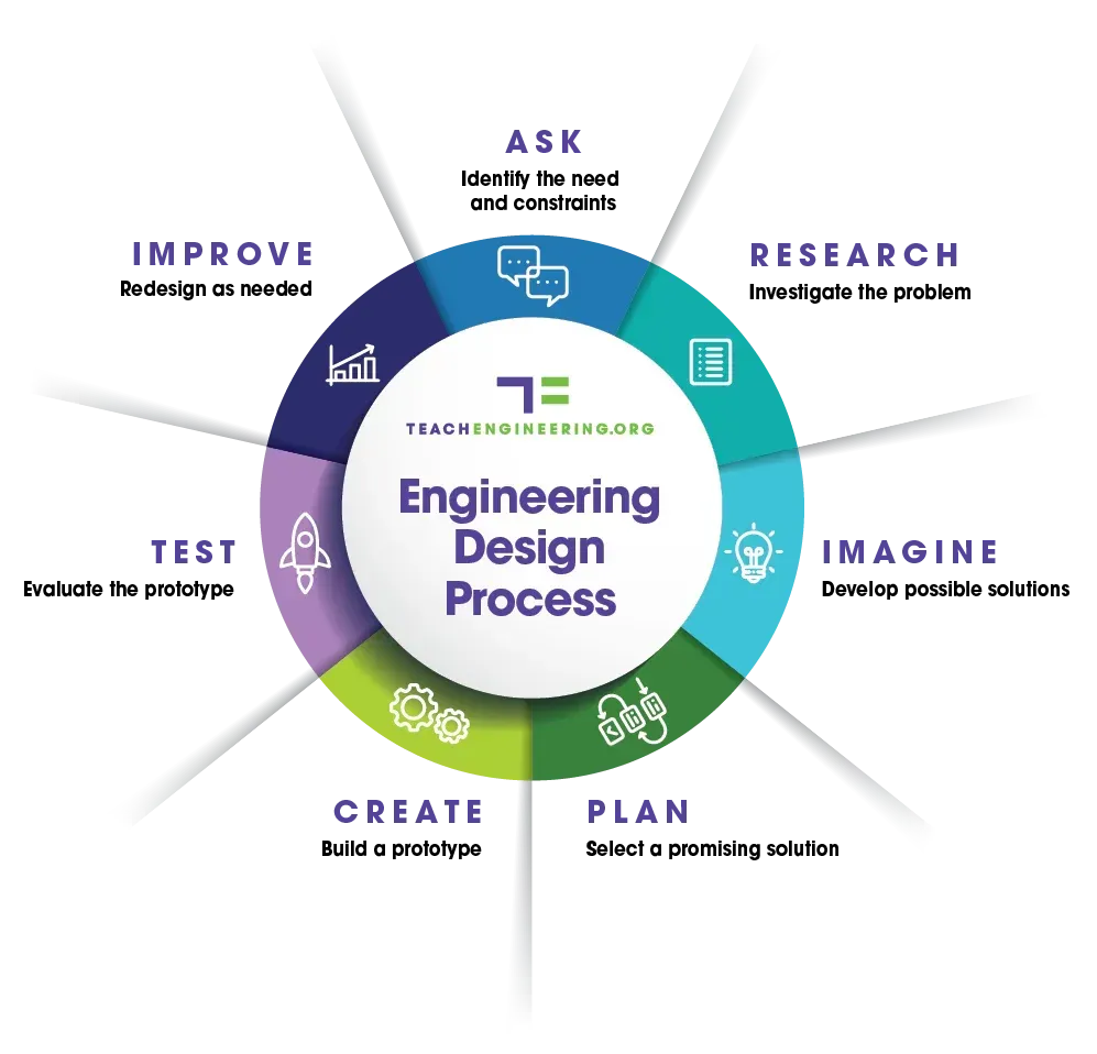
The engineering design process is iterative: testing does not merely occur at the end. It informs the next revision of the requirements, design, or build method.
Getting Started with Engineering Notebooks – VEX Library
Read VEX Library’s “Getting Started with Engineering Notebooks” to establish the practical purpose of the log: documenting decisions and evidence while the work is happening, not reconstructing a polished story later.
In “What is an Engineering Notebook?” read the definition and the discussion of what makes the record useful to another person. Then, in “Starting an Engineering Notebook,” focus on the “Choose a Format,” “Create a Simple Entry Structure,” and “Make Notebooking Part of the Routine” subsections. Finish with “From Journal to Engineering Notebook,” especially the journal distinction. As you read, notice that a short entry made immediately after a test is more valuable than a long entry recreated from memory.
A digital-first log is likely most practical for this project. It can hold photos from the iPad, screenshots of CAD dimensions, wiring diagrams, code versions, spreadsheets, and short videos. Keep it somewhere that is easy to reach during a build session. A notebook beside the bench is also valuable for quick sketches and measurements; photograph or transcribe those notes into the digital record afterward.
The format matters less than one rule:
Do not silently overwrite engineering history.
Keep the old value, decision, or test result visible, then add a dated revision explaining what changed and why.
A failed print, a motor that overheats, or an abandoned mechanism is evidence. Record it. It prevents you from repeating the same dead end and makes later troubleshooting much faster.
Build a log that matches the robot
Create one project folder or notebook called Mobile Manipulator Build Log. Inside it, use the following numbered sections. Numbering keeps the record readable as it expands.
| Section | Purpose | Typical contents |
|---|---|---|
| 00 — Project index | Lets you locate current documents and versions quickly. | Project summary, current revision, links to requirements, CAD, wiring diagram, firmware repository or archive. |
| 01 — Requirements and constraints | States what the robot must accomplish and the limits it must respect. | Reach, payload, repeatability, speed, runtime, budget or available hardware, safety constraints. |
| 02 — System architecture | Captures how major subsystems are divided. | Functional block diagram, preliminary interface table, controller allocation. |
| 03 — Design decisions | Explains why a configuration was selected. | Arm joint arrangement, gripper choice, drivetrain concept, actuator and power decisions. |
| 04 — Build records | Records fabrication, assembly, measured dimensions, and changes. | Print settings, fastener sizes, wiring changes, photos, CAD revision references. |
| 05 — Hazards and safe operation | Makes safety controls traceable and current. | Hazard register, emergency disconnect location, staged power-up procedure. |
| 06 — Tests and results | Defines planned tests and stores the actual evidence. | Test cards, measurements, plots, pass/fail decisions, photographs, fault reports. |
| 07 — Revision history and next actions | Gives a short current-status view. | What changed, why, unresolved problems, next session plan. |
You have already begun several of these sections in earlier lessons:
- the initial capability targets belong in 01;
- the functional block diagram and interface table belong in 02;
- the arm and base concepts belong in 03;
- the hazard register and staged power-up procedure belong in 05;
- the test cards from staged bring-up belong in 06.
Do not duplicate every diagram or table in several locations. Instead, give each substantial item an identifier and link or refer to its current revision. For example:
REQ-v0.1— initial project requirementsARCH-v0.1— functional architectureIF-v0.1— interface tableHAZ-v0.1— hazard registerPWRUP-v0.1— staged power-up procedureT-MB-01— mobile-base test 1T-ARM-03— arm test 3
This makes traceability possible. If T-ARM-03 reveals that a joint cannot lift the intended object, you can see which requirement was affected, what actuator was selected, and what assumption led to the decision.
Exploring VEX | Engineering Notebook
Watch VEX Robotics’ “Exploring VEX | Engineering Notebook” for a concise account of documenting the reasons for decisions, unsuccessful approaches, and planned remedies—not merely successful final work.
Watch decision evidence, where the team describes recording essential details and comparing advantages and disadvantages. Then watch what to log, focusing on the value of recording faults, planned tests, refinements, and approaches that did not work.
Populate Section 01: initial requirements and constraints
A requirement states an externally observable need. It is not a preferred component or a vague wish.
- “Use a NEMA 17 stepper” is a design choice.
- “The shoulder joint shall lift a 200 g payload at full specified reach” is a requirement.
- “The robot should be strong” is not yet a usable requirement.
- “The arm shall hold a 200 g payload at 300 mm reach for 10 seconds without visible drop or structural damage” is testable.
For every requirement, record:
| Field | Why it matters |
|---|---|
| ID | Allows tests, decisions, and revisions to refer to it precisely. |
| Requirement statement | States the needed behavior or limit. |
| Metric and threshold | Defines the quantity and what counts as success. |
| Verification method | Says how you will measure or demonstrate it. |
| Rationale/source | Records why the threshold exists. |
| Status | Draft, approved, verified, failed, or revised. |
Below is a sensible initial set for a compact desktop mobile manipulator. These are provisional targets, not measured facts. Replace any values that do not match the project you defined in the earlier lessons, but preserve the structure and record changes as revisions.
REQ-v0.1 — Initial project requirements
| ID | Requirement statement | Metric and threshold | Verification method | Status |
|---|---|---|---|---|
R-ARM-01 | The arm shall reach typical tabletop pickup locations. | Horizontal reach from base axis to tool center point of at least 300 mm. | Command or position the arm at maximum forward reach; measure base-axis to gripper reference point. | Draft |
R-ARM-02 | The arm shall manipulate small objects. | Lift and hold a 200 g test payload at a defined working reach for 10 s. | Use a known mass; observe holding behavior, joint motion, temperature, and structural deflection. | Draft |
R-ARM-03 | The arm shall return to a repeated pickup location consistently. | Over 10 repeated moves from a home position, tool center point spread no greater than 5 mm at the target. | Mark a target on the work surface; measure each final position relative to the average. | Draft |
R-ARM-04 | The arm shall move safely between two defined tabletop positions. | A no-payload move completes in 4 s or less, without collision, stall, or uncontrolled motion. | Time repeated moves using the eventual motion sequence. | Draft |
R-MB-01 | The mobile base shall travel at a useful indoor demonstration speed. | Straight-line commanded speed of at least 0.20 m/s on a smooth floor. | Time travel over a measured distance after wheel-control implementation. | Draft |
R-MB-02 | The mobile base shall operate long enough for a demonstration. | At least 20 min of the defined drive-and-sensor test profile on one charged battery. | Run the specified profile while logging voltage and elapsed time. | Draft |
R-SAFE-01 | The robot shall be capable of prompt de-energization during tests. | A main disconnect is reachable without entering the arm sweep or wheel path. | Inspect before every powered integration test. | Draft |
C-RES-01 | The first prototype shall use available workshop resources where practical. | Use the existing Raspberry Pi, electronics supply, 3D printer, and hand tools; record any purchased items. | Review bill of materials before ordering. | Active constraint |
The exact numerical targets will become more defensible when you calculate joint torque, characterize actuators, and measure the actual structure. That is normal. An early requirement is a controlled hypothesis, not a promise carved into the hardware.
When revising a requirement, do not replace R-ARM-02 without explanation. Add an entry such as:
| Revision | Change | Evidence or reason | Consequence |
|---|---|---|---|
REQ-v0.2 | Payload target changed from 200 g to 150 g. | Joint torque test showed unacceptable heating during a 200 g hold at full reach. | Update actuator comparison and repeat payload test. |
This preserves the chain of reasoning rather than disguising a limitation.
Populate Section 03: record provisional design decisions
A decision entry does not need to pretend that every alternative received weeks of research. It simply needs to state the selected approach, the reason it currently seems appropriate, and what could cause it to change.
ENGINEERING DESIGN NOTEBOOK TEMPLATE
Use the Engineering Design Notebook Template as a model for turning an open-ended robot idea into a problem summary, design brief, and repeatable test record.
On page 7, read the Step 1 prompt beginning the requirements worksheet; translate its competition-oriented language into your arm-and-base capabilities and constraints. On pages 11–13, in “Step 4 - Create a Design Brief,” read the design brief guidance, including the sketch, materials, tools, and build-procedure prompts. Finally, on page 16, inspect the testing template beginning the comparison record. Its key lesson is to preserve baseline results and modified results separately.
Create a decision table like the one below in 03 — Design Decisions. The decisions reflect a practical first prototype, and all remain provisional until the later actuator, torque, CAD, and integration tests supply evidence.
DD-v0.1 — Provisional system decisions
| ID | Decision | Current rationale | Assumptions or trade-off | Status |
|---|---|---|---|---|
DD-ARM-01 | Use a lightweight articulated arm with base yaw, shoulder, elbow, wrist pitch, and a servo-driven gripper. | Provides a useful tabletop workspace and orientation control without the complexity of a six-axis industrial-style arm. | More joints add cable-routing, power, and calibration work; payload is limited by shoulder torque. | Provisional |
DD-ARM-02 | Use a simple parallel or pinch-style gripper for the first end effector. | It is printable, easy to test on consistent objects, and suits a basic pick-and-place sequence. | It may not grip irregular, soft, or very heavy objects reliably. | Provisional |
DD-MB-01 | Use a differential-drive base with two driven wheels and a passive caster or skid support. | Independent left and right wheel speed allows straightforward steering and later odometry. | Wheel slip and uneven weight distribution can reduce straight-line accuracy. | Provisional |
DD-CTRL-01 | Assign time-critical motor, encoder, limit-switch, and safety behavior to a microcontroller; use the Raspberry Pi for higher-level sequencing, logging, and later supervision. | Keeps essential actuator control independent of non-real-time Pi processes. | Requires a reliable command and telemetry interface between boards. | Provisional |
DD-PWR-01 | Keep logic power and actuator power as separate distribution branches with a defined common reference where required. | Reduces the chance that motor or servo transients reset the controller. | Adds wiring, protection, and measurement points that must be documented carefully. | Provisional |
DD-FAB-01 | Use 3D printed brackets and mounts for early iterations, while retaining access to fasteners and allowing reprints. | The available printer supports quick mechanical changes while CAD skills develop. | Printed parts may deflect, crack, or loosen under arm loads and must be inspected. | Provisional |
A good decision entry includes the downside. For example, “differential drive is easy” is incomplete; it is useful precisely because you also record that wheel slip can limit odometry and that the arm may shift the center of mass.
For each major decision, attach evidence as it becomes available:
- a labeled sketch or CAD screenshot for geometry;
- a link to the relevant requirement IDs;
- photos of the prototype;
- a measurement table;
- a test ID that confirms or challenges the choice.
Populate Section 06: turn requirements into planned tests
A planned test is a promise to collect specific evidence later. It should be written before the result is known.
Use the test-card habits from the previous lesson: controlled configuration, safety limits, expected behavior, measurements, stop conditions, pass criterion, and result. In the build log, add a high-level test plan that links each project requirement to one or more individual test cards.
TESTPLAN-v0.1 — Verification plan
| Test ID | Requirement or decision | Controlled configuration | Measurement and pass criterion | Safety or readiness condition | Status |
|---|---|---|---|---|---|
T-ARM-01 | R-ARM-01: reach | Arm assembled, no payload, low-speed or manually positioned. | Measure maximum horizontal distance from base axis to tool center point. Pass at 300 mm or greater. | Joints secured; sweep area clear; no uncontrolled powered motion. | Planned |
T-ARM-02 | R-ARM-02: payload | Arm at defined working reach with 200 g known test mass. | Hold for 10 s. Record joint angle change, visible deflection, current if available, and temperature observations. Pass only if no stall, damaging deflection, or loss of payload occurs. | Begin at reduced risk with the payload supported; accessible disconnect. | Planned |
T-ARM-03 | R-ARM-03: repeatability | Homed arm, fixed target, 10 repeated moves from the same start condition. | Mark and measure final tool positions. Pass if spread from the average is 5 mm or less. | No payload; speed limited; travel limits active. | Planned |
T-ARM-04 | R-ARM-04: safe move time | No-payload move between two labeled positions. | Record elapsed time and inspect for collision, stalling, vibration, or cable interference. Pass at 4 s or less with no unsafe behavior. | Full staged bring-up completed first. | Planned |
T-MB-01 | R-MB-01: base speed | Base on clear, level floor; arm stowed or absent. | Measure time over a marked distance; calculate average speed. Pass at 0.20 m/s or greater. | Emergency stop or disconnect accessible; obstacle-free path. | Planned |
T-MB-02 | R-MB-02: runtime | Charged battery and repeatable driving/sensor profile. | Log start voltage, periodic voltage, elapsed time, and end condition. Pass at 20 min or longer. | Battery inspected; thermal checks scheduled; stop on low-voltage or overheating condition. | Planned |
T-SAFE-01 | R-SAFE-01: emergency disconnection | Arm and base in their intended test positions. | Verify the disconnect can be reached without entering moving zones; verify it de-energizes the intended actuator supply. | Test first with wheels raised and arm supported. | Planned |
T-PWR-01 | DD-PWR-01: separated rails | Controller active, then one actuator branch introduced according to the staged power-up procedure. | Measure logic rail before and during brief actuator motion. Pass if controller remains stable and rail remains within its allowed range. | Use the prior staged power-up test card and conservative motion limits. | Planned |
Notice the distinction between a test method and a pass criterion:
- Method: “Measure position after 10 repeated motions.”
- Criterion: “Maximum spread from the average is no greater than 5 mm.”
Without the criterion, a test produces numbers but no engineering conclusion.
At the time of testing, copy the test plan entry into a fuller test card and add actual values. Keep the original planned criterion unchanged unless you formally revise the requirement.
A completed result might later look like this:
| Field | Example result format |
|---|---|
| Test ID | T-MB-01, revision 1 |
| Date and build state | Date; chassis revision, firmware version, battery identifier |
| Actual configuration | Wheel diameter, motor driver, payload state, floor surface |
| Measurements | Distance, time for each trial, supply voltage, observations |
| Result | Pass, fail, or inconclusive |
| Interpretation | What likely caused the result and what remains uncertain |
| Next action | Proceed, revise a decision, or isolate a fault with a new test |
Do not treat “inconclusive” as failure or success. For example, if a speed test is interrupted by a loose wheel, the test did not measure drivetrain performance. Log the mechanical issue, repair it, and repeat the same test under a controlled configuration.
Make the log usable during real build sessions
A build log only works if updating it is faster than relying on memory. Use a short closeout routine after every build session, even if the session lasted only 20 minutes.
End-of-session entry format
| Field | What to record |
|---|---|
| Date and duration | When you worked and roughly how long. |
| Build state | CAD revision, wiring version, firmware version, or part revision involved. |
| Goal | One concise objective for the session. |
| Work performed | What you built, changed, calculated, or tested. |
| Evidence | Measurements, photos, screenshots, observed symptoms, or files created. |
| Decision or conclusion | What the evidence supports, rejects, or leaves uncertain. |
| Next action | The smallest useful next step, including anything blocked. |
For example:
Date: [today’s date]
Goal: CreateREQ-v0.1,DD-v0.1, andTESTPLAN-v0.1.
Work performed: Established initial targets for arm reach, payload, repeatability, arm move time, base speed, runtime, and emergency disconnection. Selected provisional arm, base, control, and power concepts.
Evidence: Project capability goals, available Raspberry Pi boards, electronics stock, 3D printer, and the safety and staged power-up procedures from earlier lessons.
Decision: Begin with a lightweight four-axis tabletop arm, pinch gripper, and differential-drive base. All actuator choices remain provisional pending torque and motor characterization.
Next action: Convert initial dimensions, masses, voltages, and component observations into a consistent unit system before estimating joint torque.
A useful log entry can be short. What matters is that it contains enough context for you to reproduce the work.
Before ending today’s session, perform this quality check:
- Every requirement has a measurable threshold and a verification method.
- Every design decision states its rationale and at least one trade-off or assumption.
- Every planned test names a pass criterion, controlled configuration, and safety condition.
- Nothing is marked “verified” unless a test result exists.
- Existing wiring, CAD, firmware, hazards, and power-up records have identifiers or links.
- The revision history states what changed and why.
Wrap-up
You now have a structured engineering build log that makes the first prototype traceable rather than mysterious.
The key habits are:
- Record requirements as measurable needs and constraints.
- Record design decisions with rationale, assumptions, and trade-offs.
- Write test plans before results exist, with explicit pass criteria.
- Keep failed tests and abandoned ideas; they are useful evidence.
- Make short entries during or immediately after work.
- Revise visibly rather than overwriting the history of the design.
Your initial log should now contain REQ-v0.1, DD-v0.1, TESTPLAN-v0.1, and a revision-history entry linking them to the safety and staged power-up records. In the next module, you will begin the applied calculations that make those entries defensible: unit conversion, equation rearrangement, and the quantities needed for forces, torques, speeds, and power.
Can't find a good explanation? Sign up and we'll make it for you
Sign up