
Hello. In the previous lesson, you converted your arm-and-mobile-base concept into an interface table: power branches, actuator commands, moving cable routes, arm mounting, controller links, and sensors. Those interfaces are also the places where hazards concentrate. A battery connector can short, a cable can snag in a joint, a software fault can command motion, and an arm mount can loosen under load.
This lesson turns the design into an initial hazard register. You will identify foreseeable mechanical, electrical, thermal, and motion hazards, then assign controls that reduce the chance or consequence of harm. The aim is not to make a formal industrial safety certification; it is to establish safe design requirements and working practices before you begin fabricating and energizing the robot.
Hazard, event, and risk
A hazard is something with the potential to cause harm. The hazard is not merely “the robot”; it is a specific source of harm, such as stored battery energy, a hot motor driver, a moving link, or a sharp printed edge.
A useful entry separates three things:
- Hazard source — for example, a powered shoulder joint.
- Hazardous event or exposure — the joint moves unexpectedly while your hand is near its linkage.
- Possible harm — pinching, impact, or crushing of a finger.
A risk is the combination of how serious that harm could be and how likely the event is during a particular task. Risk is often greatest during setup, wiring, code changes, calibration, and troubleshooting, because those activities put a person close to an unfinished machine.
The University of Illinois robotics-safety guidance gives a useful overview of these practical hazards and the idea that safety needs to be designed in rather than added after an incident.
Robotics Safety | Office of Safety | Illinois
Read “Robotics Safety” from the University of Illinois Office of Safety. It connects ordinary robot-build activities—testing, programming, maintenance, and setup—to the common hazards and the control hierarchy you will use in your own register.
In the “Hazards” section, read the hazard overview. Then read the “Hazard Controls” section, especially “Elimination,” “Substitution,” and “Engineering Controls,” from the control hierarchy. Finish with “Administrative Controls,” “Risk Assessment,” “Standard Operating Procedures,” and “Personal Protective Equipment.” Focus on the difference between changing the machine, changing the way it is operated, and protecting the person.
A hazard register should be attached to real tasks, not written as a generic list. For this project, your initial tasks include:
- fabricating and assembling 3D-printed arm and chassis parts;
- wiring and testing the battery, regulators, and motor drivers;
- bench-testing individual motors and servos;
- calibrating joints with the arm supported or partially assembled;
- driving the mobile base in a defined test area;
- charging and storing the selected battery pack.
The OSHA robotics guidance also makes an important point for a small robot: a robot’s hazardous space is larger than its base footprint. The arm, gripper, carried object, and mobile chassis can all enter that space. Call the maximum region reachable by the arm, gripper, payload, and base its operating envelope for this project. Keep people, loose tools, cables, and fragile equipment outside that envelope whenever motion is enabled.
Choose controls in the right order
When you find a hazard, do not jump immediately to “wear gloves” or “add a warning label.” First ask whether the source of harm can be removed or reduced by design. The hierarchy below ranks controls by their usual reliability.
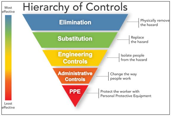
| Control level | Meaning for your robot project | Example |
|---|---|---|
| Elimination | Remove the hazardous feature or exposure entirely. | Do not use a cutting or sharp-tool end effector in this first build; do not allow autonomous motion during wiring. |
| Substitution | Replace the hazard with a less hazardous alternative. | Use compliant rubber jaw pads or a soft object for early gripper tests rather than rigid jaws gripping hard parts. |
| Engineering control | Change hardware or its physical behavior so exposure is reduced. | Fuse near the battery, guard a pinch point, add a mechanically secured arm mount, limit speed, or provide an emergency-stop circuit. |
| Administrative control | Change the procedure: rules, checklists, training, labels, or test sequence. | One operator controls a powered test; use a low-speed test mode; inspect fasteners before operation. |
| PPE | Protect the user from remaining risk. | Safety glasses during first structural or payload tests. |
The levels are not mutually exclusive. A sound control plan uses layers. For instance, a gripper test may use compliant jaw pads, a mechanical travel limit, a low-speed mode, a clear-workspace rule, and safety glasses for initial testing.
PPE is the last layer, not permission to work carelessly. In particular, avoid loose gloves, sleeves, jewelry, or long unsecured hair near rotating wheels, gears, or moving joints. Gloves may be appropriate only when the robot is disconnected from power and you are handling sharp edges or hot components.
The four hazard families in your planned build
Mechanical hazards: failure, pinch points, and ejected parts
Mechanical hazards exist even when the robot is unpowered. A poorly printed arm bracket can crack under a payload; an inadequately retained wheel can detach; a gripper can drop its object; and accessible gears or linkages can pinch fingers.
For your arm, pay particular attention to:
- the arm pedestal and J1 mount on the chassis;
- shoulder-link and elbow-link fasteners, shafts, bearings, and printed brackets;
- gripper jaws, linkages, and any exposed gear or belt drives;
- a payload that could fall or be flung during a sudden stop;
- cable routing that can be pulled, cut, or trapped by a joint.
The best mechanical controls begin in CAD and component selection. Keep the early payload modest, support gravity-loaded links during calibration, use positive fastener retention where appropriate, and make fasteners accessible for inspection. Do not treat a press fit, hot glue, or friction alone as the sole retention method for a load-bearing or rotating component.
A printed structural part also needs a controlled test. Before operating the whole arm, test each joint at low speed with no payload, then with a known small test load. Stop the test if you see cracking, excessive bending, loose hardware, a shifting bearing, or a change in alignment.
Electrical hazards: shorts, reverse polarity, and energized work
Most of the robot may operate at extra-low DC voltage, but that does not make it harmless. A battery pack can supply enough current to heat wires, vaporize a poor connection, start a fire, or damage electronics. Mains-powered chargers and power supplies introduce a separate shock hazard: do not open or modify them.
Your highest-priority electrical interfaces are P-01 from battery to power distribution, P-02 to actuator drivers, and P-03 to regulated logic power. Design requirements for them include:
- a polarized battery connector;
- a fuse close to the battery’s positive terminal;
- insulation over conductive terminals;
- wire, connectors, and switches rated for the eventual voltage and current;
- strain relief so a cable cannot pull out of a terminal;
- an accessible main disconnect;
- no wiring changes while the battery is connected;
- a current-limited bench supply or protected first-power test where practical.
Reverse polarity deserves a specific register entry. It is easy to make during a fast prototype build, and its effects can be immediate. Use keyed connectors where possible, clearly mark polarity, and verify with a multimeter while the circuit is unpowered before connecting the battery.
Thermal hazards: batteries, wiring, motors, and electronics
Heat is usually a symptom before it becomes a failure: excessive motor current, undersized wiring, a loose high-resistance connector, inadequate motor-driver cooling, or a damaged battery. Treat unexpected heat as a fault condition, not as normal behavior to ignore.
Potential thermal sources in this build include:
- a lithium-polymer battery, if selected;
- motor-driver transistors and voltage regulators;
- motors stalled against a mechanical stop;
- undersized wires, connectors, or solder joints;
- the 3D printer hot end, heated bed, and moving axes during fabrication.
A thermal control plan contains both prevention and detection. Prevention includes current budgeting, correct conductor sizing, fusing, ventilation, avoiding motor stalls, and respecting component temperature limits. Detection includes touching nothing energized, but inspecting for heat only after disconnecting power, measuring temperature when appropriate, logging overcurrent or driver fault states, and stopping a test when a part becomes unexpectedly hot or smells abnormal.
If you choose a LiPo battery, it warrants its own control measures. The battery must be physically inspected before use; a swollen, punctured, crushed, or damaged pack must not be charged or used. Charge only with equipment and settings intended for the battery’s chemistry and cell count, on a non-flammable surface, under active supervision.
Watch “Safely Using LiPo Batteries” by DroneBot Workshop for a focused introduction to protected first power-up and supervised LiPo charging. Use this if LiPo is a candidate chemistry for the mobile base; if you choose another battery chemistry, follow that battery manufacturer’s specific instructions instead.
First watch first power protection, which shows the purpose of a fast-acting fuse during initial assembly. Then watch safe charging. Focus on correct charger settings, battery inspection, a non-flammable charging surface, and the rule never to leave an active charge unattended. Manufacturer instructions for your actual pack and charger take priority over general video guidance.
Motion hazards: impact, crushing, and unintended travel
Motion hazards are the most visible robot-specific hazard. They include the arm swinging into a hand, the mobile base rolling unexpectedly, a gripper closing on an object or finger, and an unintended restart after a program change or communications problem.
Do not assume that “small” means harmless. A modest arm can move quickly at its gripper because several joints contribute to the motion, and a loaded arm has gravity and inertia. A stopped motor also does not guarantee instant safety: the arm may coast, flex, or fall under gravity after power is removed.
Your early motion controls should include:
- a defined, clear operating envelope;
- low-speed, low-acceleration testing;
- the arm unloaded or carrying only a soft, light test object;
- base wheels raised off the bench for early drivetrain tests;
- an accessible means to stop actuator motion;
- software travel limits plus independent physical measures where appropriate;
- a rule that hands stay outside the envelope while drive power is enabled;
- manual or low-energy operation for alignment, measurement, and cable routing.
A useful emergency stop is an engineering control, but it must be designed for the real power system. It should not be merely a software button on the Raspberry Pi screen. In an appropriate design, the emergency-stop device opens a normally closed safety circuit that independently disables actuator drive power or de-energizes a suitably rated contactor. The exact wiring, ratings, and power architecture will be developed in the power module.
Wire Emergency Stop (E-Stop) Guide (A Must for Anyone Doing Hardware)
Watch “Wire Emergency Stop (E-Stop) Guide” by Kevin Wood | Robotics & AI to understand the basic normally closed safety-loop idea and why higher-current systems need a suitably rated switching device.
Watch normally closed contacts for the basic behavior: an unpressed button maintains a circuit, while pressing it breaks that circuit. Then watch contactor sizing, focusing on the distinction between the E-stop contact rating and the current handled by a contactor. Finish with status monitoring to see how a second contact can report E-stop status to the controller. Treat this as a topology demonstration, not a final wiring prescription: your eventual switch, fuse, contactor or driver-disable circuit must be rated for the selected DC voltage, current, and interruption duty.
An E-stop is not a substitute for low-risk test conditions. Pressing it removes or disables drive energy, but a joint may still coast or drop. For a gravity-loaded arm, reduce the stored mechanical energy in the first place: use low test speeds, keep payloads light, support the arm where necessary, and stay out of its fall path.
Create Hazard Register 0.1
Add a new section to your build log titled Hazard Register 0.1. Connect each hazard to the interface IDs from the previous lesson. This makes the register actionable: when you select a battery, revise P-01; when you finalize the arm mount, revise M-01; when you choose a motor driver, revise S-01 and S-02.
Use the following as the initial register for the provisional four-axis arm, gripper, and differential-drive base. Entries marked TBD are requirements to close before that subsystem is operated.
| ID | Interface(s) | Category | Hazardous event and possible harm | Controls assigned now | Verification and status |
|---|---|---|---|---|---|
| HZ-01 | M-01, M-02, S-02 | Mechanical / motion | Arm, wrist, or gripper contacts or traps a hand during calibration; a gravity-loaded link falls after loss of drive power. | Eliminate powered adjustment where possible. Use low-speed, unloaded testing; keep hands outside the envelope; define software travel limits; provide an accessible actuator stop; support the arm during alignment. Use compliant jaw pads for early gripper tests. | Demonstrate each joint at low speed with no payload. Confirm stop action and inspect for a safe post-stop position. TBD actuator and stop design |
| HZ-02 | M-01, M-02, M-04 | Mechanical | Arm mount, shaft, printed bracket, fastener, or payload fails; component or object falls or is ejected. | Use positive retention and accessible fasteners; inspect printed parts for cracks; keep early payload below the design target; perform staged static-load and slow-motion tests; keep observers clear during first load tests. | Record fastener inspection and test load. Stop if deformation, loosening, or misalignment occurs. Constraint |
| HZ-03 | M-03, S-01, S-04 | Motion | Base rolls unexpectedly, collides with a person or object, catches a cable, or leaves the bench. | Raise driven wheels for first bench tests; test at low speed in a clear floor zone; use one active operator; establish a physical boundary; disable drive before handling wheels or wiring. | Verify each wheel direction with wheels raised. Conduct the first floor test with no arm payload. Constraint |
| HZ-04 | P-01, P-02, P-03 | Electrical / thermal | Short circuit, reverse polarity, damaged insulation, or a loose high-current joint causes burns, fire, or equipment damage. | Fuse near battery positive; use polarized connectors and insulated terminals; provide strain relief and main disconnect; verify polarity unpowered; use protected or current-limited initial power-up where possible; never alter wiring with battery connected. | Check continuity only while de-energized; document fuse, connector, and wire ratings after selection. TBD component selection |
| HZ-05 | P-01 | Thermal / electrical | Damaged or incorrectly charged LiPo battery overheats, vents, or catches fire. | If LiPo is selected: inspect before every use; use a compatible balance charger and correct settings; charge outside the robot on a non-flammable surface under supervision; remove damaged or swollen packs from service; follow local disposal rules and manufacturer instructions. | Create battery inspection and charging checklist before buying or using the pack. Conditional on LiPo selection |
| HZ-06 | P-02, S-01, S-02 | Thermal | Stalled motors, overloaded drivers, regulators, wiring, or connectors overheat. | Select components from a later current budget; fuse branches; avoid sustained stalls; provide ventilation or heatsinking if required by the datasheet; set conservative initial duty cycle and runtime; stop on fault or unexpected heating. | Run short, unloaded tests first; inspect after power-off; later measure current and temperature under representative load. TBD measurements |
| HZ-07 | D-01, S-01, S-02, S-03 | Motion / control | Bad command, wrong program state, failed communication, or incorrect pin mapping causes unintended motion. | Start with one subsystem and one actuator at a time; use a clearly labeled test mode; require a deliberate enable action; limit speed; verify physical direction before increasing power; define loss-of-command behavior as a design requirement. | Record successful low-speed direction test for every axis and wheel. TBD control implementation |
| HZ-08 | Fabrication work | Thermal / mechanical | Contact with 3D-printer hot surfaces or moving axes; burns from freshly printed parts; cuts from tools or sharp edges. | Follow printer manufacturer procedures; keep hands clear during operation; allow parts to cool; remove sharp edges; keep the print area clear; do not leave equipment operating contrary to its manufacturer guidance. | Add printer-specific precautions and inspection to the build log. Ongoing |
Two principles are worth preserving as you update this table:
- A control is not complete until it has a verification method. “Add a fuse” becomes meaningful only when you specify its location, rating basis, installation check, and test.
- A control should be assigned before the risky activity begins. “We will be careful” is not an adequate control for an unfused battery lead or an arm that can strike someone during a calibration test.
Turn the register into a working procedure
Your hazard register will become useful only if it changes what you do at the bench. Create a short pre-power checklist for the next lesson. Keep it to a single page and attach it to your build log.
For the first powered test of any subsystem, include these checks:
- The work surface is clear, dry, and free of loose conductive parts.
- The robot or test mechanism is secured so it cannot move unexpectedly.
- The operating envelope is clear of hands, tools, and bystanders.
- Battery polarity, connector condition, insulation, and fuse placement have been checked with power disconnected.
- A main disconnect or emergency stop is accessible before drive power is enabled.
- The initial command is low speed, low acceleration, and no payload.
- Only one person gives motion commands; other people remain clear.
- If unusual sound, heat, smell, vibration, or motion occurs, disconnect drive power and investigate before trying again.
This checklist is an administrative control. It supports the physical controls; it does not replace them.
Add this revision entry to the build log:
| Revision | Change | Reason |
|---|---|---|
| 0.3 | Created Hazard Register 0.1 and pre-power checklist for the arm, gripper, mobile base, battery system, and fabrication work. | Identifies foreseeable hazards before fabrication and assigns design or procedural controls with verification steps. |
Wrap-up
You have now identified the principal safety concerns in the planned mobile manipulator:
- Mechanical hazards include structural failure, pinching, falling links, and ejected payloads.
- Electrical hazards include battery shorts, reverse polarity, exposed conductors, and energized modifications.
- Thermal hazards arise from batteries, stalled motors, drivers, regulators, wiring, and fabrication equipment.
- Motion hazards include unexpected arm or base movement, collision, trapping, and movement after a control or power fault.
- The most reliable controls remove or reduce hazards through design; procedures and PPE provide additional layers rather than the main defense.
- Each safety control needs a clear verification step and should be linked to the relevant mechanical, power, signal, or data interface.
Next, you will use this register to apply a staged power-up procedure: testing one unpowered or low-energy subsystem at a time before integration.
Can't find a good explanation? Sign up and we'll make it for you
Sign up