
Hello. Your previous concept sheet chose a four-axis arm with a parallel-jaw gripper on a differential-drive base. It identified the major subsystems, but it did not yet state exactly how those subsystems meet. That missing layer is where many practical build failures originate: a motor supply that cannot support a driver, a Raspberry Pi logic pin exposed to an incompatible voltage, an arm mount with no defined bolt pattern, or a sensor cable with no planned route through moving joints.
This lesson turns the concept into an interface table: a compact engineering record of every important mechanical, power, signal, and data connection between your subsystems. You will create a revision 0.1 table that is specific where your design is decided and explicitly marked TBD where later measurements or component selection are still needed. This should take about 40 minutes, including updating your build log.
From a functional diagram to a build contract
A functional block diagram answers: What must each subsystem do?
An interface table answers: What must be true where two subsystems connect for them to work together safely?
Think of an interface as a contract. The chassis may provide a mounting surface for the arm, but the interface is not adequately defined by writing “arm attaches to chassis.” You need enough information for a future version of you to fabricate, wire, test, and replace the connected parts without relying on memory.
A useful interface entry normally identifies:
- the two connected subsystems;
- the purpose of the connection;
- the direction of control or information, where applicable;
- the physical connection method;
- electrical, data, or mechanical constraints;
- a verification method;
- what remains undecided.
Read this brief checklist before constructing your own table.
Interface control document - Wikipedia
“Interface Control Document” on Wikipedia provides a concise systems-engineering checklist. Read it to distinguish the different kinds of interfaces and to see the level of detail an interface record can contain.
In the “Typical content” section, read the scope checklist. Notice that signals, connectors, units, limits, update rates, and change history are all potentially part of an interface. Then read the “Types of documented interfaces” section, from the interface categories. For this project, concentrate on physical or mechanical, electrical power, signals, communication data, and the hardware-software boundary.
For the mobile manipulator, use these four categories consistently.
| Interface type | What crosses the boundary | Typical examples in this project | Information worth recording |
|---|---|---|---|
| Mechanical | Force, position, motion constraint, physical support | Chassis to arm pedestal; wrist to gripper; motor to wheel bracket | Bolt pattern, datum faces, alignment, allowable mass/load, clearances, cable exit direction |
| Power | Electrical energy | Battery to power distribution; power supply to motor driver; regulated rail to controller | Voltage range, polarity, expected continuous and peak current, fuse, wire/connector, return path |
| Signal | A single control or measurement waveform | PWM or direction commands; limit switches; encoder channels | Source and receiver, voltage level, polarity, pull-up requirement, timing, connector pins |
| Data | Encoded multi-value messages governed by a protocol | Raspberry Pi to microcontroller serial messages; I2C distance sensor | Bus/protocol, message contents, update rate, physical transport, valid ranges, fault behavior |
A data interface always travels through physical electrical signals, but document it separately because its important questions are different. A limit switch might simply be open or closed; a serial telemetry message might contain joint states, wheel speeds, and fault flags in a defined format.
Decide what belongs in revision 0.1
Your current design is intentionally provisional. You do not yet know final actuator models, battery voltage, wire sizes, motor-driver part numbers, or every connector. An interface table should expose those gaps rather than conceal them.
Use one of these labels in the status column:
- Confirmed — established by hardware you already own or a deliberate design decision.
- Constraint — must be true, even though the selected component is not final.
- TBD — requires a later selection, calculation, measurement, or test.
- Assumption — a temporary value used to continue design work; it must eventually be validated.
For example:
- Good: “Motor rail voltage: TBD; must lie within selected driver and motor operating ranges.”
- Good: “J1 axis must remain vertical within the assembly tolerance to be defined after bearing and bracket selection.”
- Poor: “Motor power: 12 V,” if you have not selected a motor, driver, and battery.
- Poor: “Arduino to Raspberry Pi: serial,” without saying whether that means USB serial or bare UART pins, or whether their voltage levels are compatible.
The point is not bureaucracy. It is to prevent an assumption from silently becoming a build error.
Name subsystems before naming connections
Use stable names in the left-hand column. For the concept from the previous lesson, a practical starting set is:
| Code | Subsystem |
|---|---|
| BAT | Battery pack and main disconnect |
| PDB | Power-distribution and protection assembly |
| REG | Regulated low-voltage supply |
| PI | Raspberry Pi supervisory computer |
| MCU | Microcontroller for time-critical I/O and motor control |
| BASE-DRV | Differential-drive motor-driver assembly |
| L-MOTOR / R-MOTOR | Left and right wheel gearmotors with encoders |
| ARM-DRV | Arm actuator drivers or servo-control distribution |
| ARM | Arm structure, joints, and moving cable harness |
| GRIP | Gripper and its actuator |
| RANGE | Forward obstacle or distance sensor |
| HOME | Arm home or end-stop switches |
An interface ID should state neither a wire color nor a final connector model. Instead, give it a durable name such as P-01 for power, S-02 for a signal, D-01 for data, and M-01 for mechanical.
Mechanical interfaces: fit, alignment, load, and motion
Mechanical interfaces are easy to under-document because they are visible. Yet a hole pattern that is not referenced to a datum, or a gripper whose tool-center offset is never measured, will later create errors in assembly and kinematics.
For every mechanical interface, record four ideas:
-
How parts attach
Fastener count, fastener size when known, mounting-face geometry, bearing fit, clamp method, or shaft coupling. -
How parts align
Define a reference face, centreline, or coordinate. For example, the J1 yaw-axis centreline must be located relative to the chassis centreline. -
What loads and constraints matter
Arm mass, payload-induced moment, allowable deflection, wheel-axle alignment, or a gripper mass limit. -
What must stay clear
Joint travel, fastener access, cable bend space, battery enclosure, wheel guards, and sensors.
The arm-to-chassis connection is particularly important. It must carry the complete arm mass plus the bending moment created when the arm reaches outward with a payload. Its interface description should therefore include a mounting pattern, a flat mounting surface, the J1-axis location, and accessible fasteners. It should also specify that the arm may not sweep into the battery, wheel guards, sensor mount, or electronics enclosure.
The wrist-to-gripper connection deserves equal care. The gripper’s tool centre point is not necessarily at the wrist pivot. Record the tool offset as a measurement requirement. Later, kinematics will use that measured offset to predict where the fingertips actually go.
A formal template can be much larger than a hobby project needs, but its mechanical and electrical checklists are useful.
Interface Control Document Template ...
This Interface Control Document template illustrates the details that professional projects capture at subsystem boundaries. Use it as a checklist, not as a demand to create a seven-page document for every connection.
On page 4 of 7, in Section 3.3, “Critical dimensions,” read the mechanical checklist. Apply its ideas of attachment points, frame of reference, mass, and mounting specifications to the chassis-to-arm and wrist-to-gripper interfaces. Then move to pages 5–6 of 7, Section 4, “Electrical Interface.” First read the block-diagram criteria. Next read the connector checklist, followed by the pin-level checklist. For your first revision, record only details that are known and mark the rest as TBD.
Power interfaces: energy has a source, branch, load, and return
A power entry must say more than “connect positive and negative.” At minimum, document:
- source and load;
- nominal voltage and permitted range;
- polarity;
- continuous and peak current requirement;
- connector and wire details when selected;
- fuse or protection location;
- return path and grounding requirement;
- conditions for safe connection or disconnection.
For this project, maintain a conceptual separation between:
- Battery and high-current motor power — battery, power distribution, motor drivers, wheel motors, and any high-power arm actuators.
- Regulated logic power — Raspberry Pi, microcontroller, low-power sensors, and the logic side of motor drivers.
- Control signals and data — command, encoder, and communications wiring.
“Separate” does not mean that every ground is disconnected. A motor-driver control input normally needs a valid electrical reference to the microcontroller sending it. The actual return and grounding arrangement must follow the selected driver documentation, while high motor-current paths should be planned so they do not share long, noisy sections of wiring with sensitive sensor returns.
The wiring diagram below shows this distinction in a stepper system. Its component choices are not your final design; treat it as a topology example.
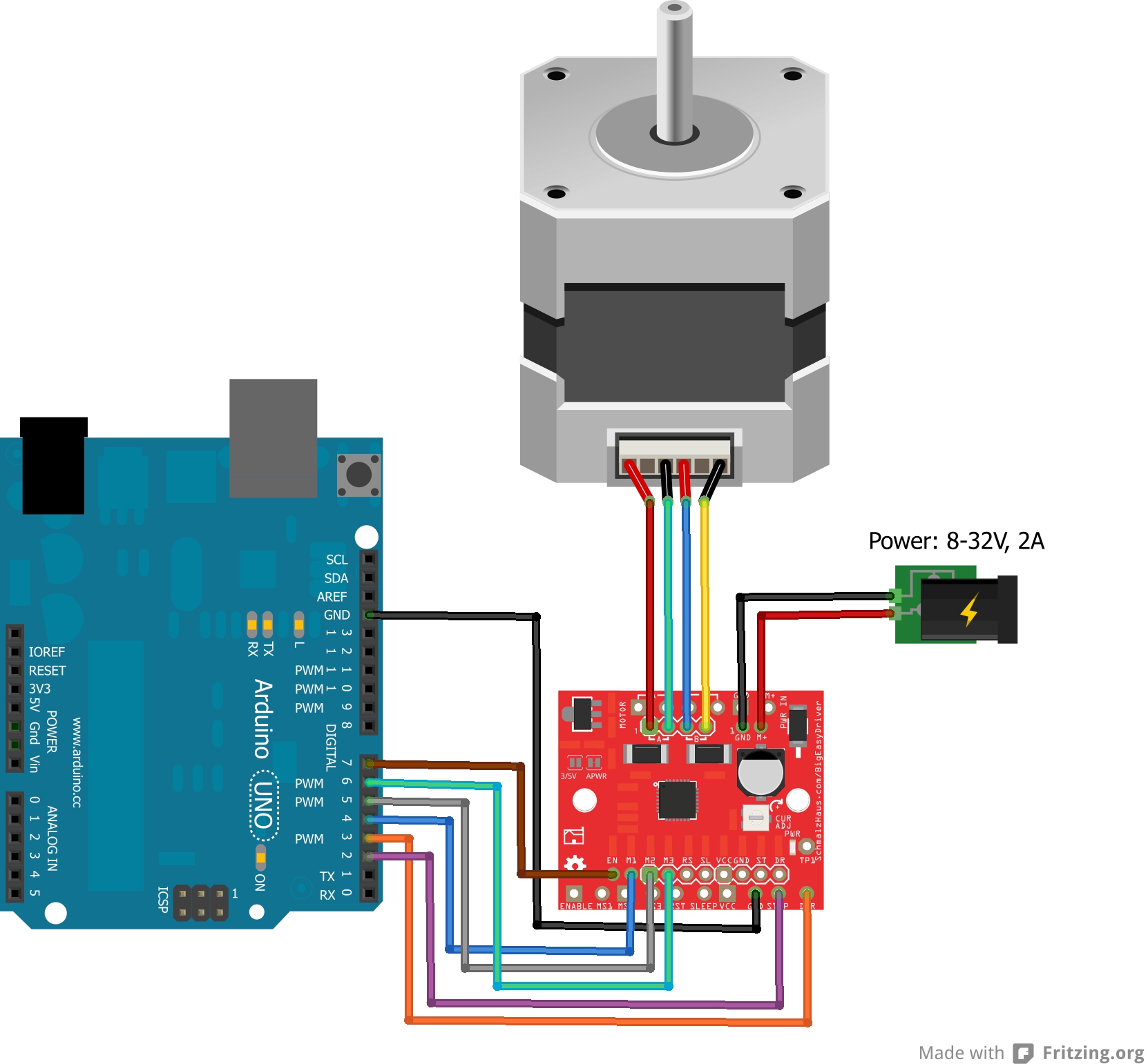
Notice three separate contracts in the diagram:
- The motor supply to driver connection must meet voltage, current, polarity, and protection requirements.
- The controller to driver connection must meet control-signal and reference-ground requirements.
- The driver to motor connection must preserve correct coil pairing and be secure enough for motor current and vibration.
Do not copy the shown microcontroller pin assignments into your own table. Your selected drivers and control strategy will determine those details.
A practical rule: do not plug or unplug motor leads while the motor driver is powered. Record that operating constraint in your build log and later power-up procedure.
Signal and data interfaces: specify direction and behavior
Signal interfaces usually cause trouble through unstated voltage or timing assumptions. For every signal, identify:
- producer and receiver — who sends and who receives;
- purpose — enable, position command, encoder feedback, limit detection;
- logic level — such as 3.3 V or 5 V, once known;
- electrical behavior — push-pull, open-drain, pull-up, normally open/closed switch;
- timing — pulse width, maximum update rate, edge counting, debounce expectation;
- safe state — what the actuator or software should do if the signal is absent.
For example, a limit-switch interface may eventually specify that the microcontroller reads a normally closed switch with an internal or external pull-up resistor. A broken cable then appears as an active fault instead of falsely appearing safe. That is a design choice to record, not an automatic rule for every circuit.
For digital data, add protocol-level information:
- physical transport: USB serial, UART, I2C, SPI, or another selected method;
- sender and receiver;
- message types;
- update rate and expected latency;
- validation or acknowledgement rule;
- timeout and fault behavior.
The Raspberry Pi can supervise high-level behavior, while the microcontroller handles actuator timing and immediate sensor input. Their eventual data link should be recorded in this lesson even if its message format is not designed until the embedded-control module.
One important constraint is already known: Raspberry Pi GPIO uses 3.3 V logic. If you choose a direct UART connection to a 5 V microcontroller board, its transmit output must not drive the Pi receive pin at 5 V. Your table should state “logic-level compatibility or level conversion required.” If you use USB serial, the electrical boundary is handled through the USB interface rather than direct GPIO UART pins.
Your Interface Table 0.1
Copy the following into your engineering build log. This is a coherent starting version for the provisional arm and mobile base. Replace the entries marked TBD as you select parts and take measurements.
| ID | Connected subsystems and purpose | Type | Interface specification for revision 0.1 | Verification and status |
|---|---|---|---|---|
| M-01 | Chassis / ARM: supports arm pedestal and defines J1 location | Mechanical | Rigid pedestal mounting face; bolt count, bolt size, and pattern TBD. Define J1 centreline relative to chassis centreline and a chassis datum edge. Require fastener access, no interference through intended J1 range, and load capacity for arm plus payload. | Assembly fit check; measure J1-axis position and inspect full arm sweep. Constraint |
| M-02 | ARM wrist / GRIP: mounts gripper and locates tool centre point | Mechanical | Repeatable wrist flange or bracket; fastener pattern TBD. Record gripper mass limit after actuator selection. Measure wrist-pivot to tool-centre offset and define cable exit direction. | Test fit; measure tool offset; sweep wrist through full range. TBD dimensions |
| M-03 | Chassis / L-MOTOR and R-MOTOR: mounts drivetrain and aligns wheels | Mechanical | Motor-bracket geometry and wheel-axle centreline TBD. Left and right wheel axes must be parallel; wheels must clear chassis and wiring. Provide access for wheel removal and encoder cable strain relief. | Check axle alignment and free wheel rotation. Constraint |
| P-01 | BAT / PDB: distributes stored energy into protected branches | Power | Battery chemistry, nominal voltage, capacity, and connector TBD after current budget. Use a polarized connector, a main disconnect, and a fuse located close to the battery positive terminal. Record continuous and peak current limits when selected. | Confirm polarity before connection; verify fuse rating and connector keying. TBD selection |
| P-02 | PDB / BASE-DRV and ARM-DRV: supplies high-current actuator power | Power | Separate fused branches for base drive and arm actuation. Branch voltage must satisfy the selected driver and actuator limits. Record wire gauge, connector, peak current, and return path after selection. | With no motors commanded, measure branch voltage and polarity at each driver. Constraint |
| P-03 | REG / PI, MCU, RANGE, logic side of drivers: powers logic electronics | Power | Regulated rail or rails appropriate to selected boards. Raspberry Pi supply requirements and microcontroller supply requirements must be recorded separately. Keep this distribution distinct from high-current motor branches. | Measure regulated voltage at each load while motors are inactive, then later under load. TBD selection |
| S-01 | MCU / BASE-DRV: commands left and right wheel drive | Signal | MCU sends two independent wheel commands. Exact interface may be PWM plus direction or the selected driver’s equivalent. Record pins, voltage compatibility, enable behavior, polarity, and required safe state. | Command each wheel at low power; verify forward command gives intended physical direction. TBD driver |
| S-02 | MCU / ARM-DRV: commands J1–J4 and gripper actuation | Signal | Five logical command channels planned: J1, J2, J3, J4, and gripper. Command type, signal levels, pins, and update timing depend on actuator choice. Arm must default to a defined safe state when control is unavailable. | Bench-test one channel at a time with the actuator unloaded. TBD actuator choice |
| S-03 | HOME / MCU: detects arm home or end-stop condition | Signal | One input per homed joint as required. Select normally open or normally closed wiring later; record switch voltage level, pull-up or pull-down method, connector, cable route, and debounce method. | Manually actuate each switch and confirm the microcontroller detects only its intended input. TBD switch choice |
| S-04 | L-MOTOR and R-MOTOR encoders / MCU: reports wheel rotation | Signal | Each encoder supplies its selected output format, commonly A/B quadrature channels. Record logic voltage, connector, channel count, counts per revolution, and cable routing away from motor-power conductors. | Rotate each wheel by hand and confirm count direction and response. TBD motor choice |
| D-01 | PI / MCU: exchanges supervisory commands, telemetry, and fault state | Data | Transport TBD: USB serial or direct UART are candidate options. If direct UART is used, require 3.3 V logic compatibility or level conversion. Message format, update rate, acknowledgements, and timeout behavior are to be defined in the embedded-control module. | Establish a reliable test message in both directions after transport selection. TBD protocol |
| D-02 | RANGE / MCU: provides forward obstacle measurements | Data | Sensor model and bus TBD. Record whether it uses I2C, UART, or discrete trigger/echo signals; record voltage compatibility, address or pin assignment, useful measurement range, and mounting orientation. | Compare readings with a measured target distance after sensor selection. TBD sensor |
| M-04 | ARM moving links / cable harness: protects and routes actuator and sensor wiring | Mechanical | Route cables along the arm with strain relief at fixed and moving ends. Preserve full joint travel, minimum bend radius, and clearance from pinch points. Service loops and connector locations TBD. | Move each joint through its full range unpowered; inspect for tension, abrasion, and snagging. Constraint |
A few choices in this table are deliberately expressed as requirements rather than hardware facts. For instance, you have not yet selected the arm actuators, so it would be misleading to declare a particular servo voltage or stepper-driver current limit. But it is already valid to require five independent actuator command channels and a safe response to loss of control.
Audit the table against your concept sheet
Before ending the session, carry out this short design activity.
-
Add the interface IDs
M-01throughD-02to the relevant locations on your concept sheet. PutM-01at the arm pedestal,M-02at the wrist, and so on. -
Add any connection specific to hardware you already own. For example, if your wheel motors include encoders, create separate left and right encoder entries if they have separate plugs.
-
Look at each subsystem and ask four questions:
- What mechanically supports it?
- What powers it?
- What signals command it or report its state?
- What data does it exchange, if any?
-
For every moving cable, identify both strain-relief points and the joints it crosses. A wire route is not complete merely because the endpoints are listed.
-
Add this revision record to the build log:
| Revision | Change | Reason |
|---|---|---|
| 0.2 | Created provisional interface table for arm, gripper, differential-drive base, controllers, sensors, and power distribution | Converts the system concept into testable subsystem-boundary requirements |
Your table is complete enough for this stage if it makes every major boundary visible and makes uncertainty explicit. It is not supposed to contain every final pin number yet.
Wrap-up
You have now converted the arm-and-base concept into a set of engineering contracts:
- Mechanical interfaces define mounting, alignment, load path, clearance, and moving-cable constraints.
- Power interfaces define source, voltage, current, polarity, protection, and return path.
- Signal interfaces define who sends a control or measurement waveform, along with logic-level and safe-state requirements.
- Data interfaces define the transport and the future need for message format, update rate, and fault handling.
- A useful early interface table is candid: it distinguishes confirmed decisions from constraints, assumptions, and TBD selections.
In the next lesson, you will use this table and your concept sheet to identify mechanical, electrical, thermal, and motion hazards, then assign a concrete control measure to each.
Can't find a good explanation? Sign up and we'll make it for you
Sign up