
Hello. In the previous lesson, you separated the mobile manipulator into mechanical, electrical, sensing, control, and software domains. That functional architecture tells you what each part of the system must do. Now you will make the first physical concept: the arm’s joint layout, its gripper, and the differential-drive chassis that carries it.
The target is not a final CAD model or component list. It is a provisional concept that can meet the requirements you wrote earlier, exposes the important trade-offs, and gives the next design steps a stable starting point.
By the end of this lesson, you will have a one-page concept sketch specifying:
- a practical arm arrangement and its motion axes;
- a simple, adaptable end effector;
- a stable, buildable differential-drive base layout;
- the key dimensions, assumptions, and “to be decided” items that must be resolved later.
Choose motion from the task, not from the number of motors
An arm has a degree of freedom (DOF) for every independent motion axis. A rotary joint contributes one rotational DOF; a linear slide contributes one translational DOF. The important design question is not “How many axes can I fit?” but:
What positions and tool orientations must the gripper achieve while carrying the required payload?
Watch this short visual introduction before committing to a layout.
Robot Axes Explained | Degrees of Freedom, Pitch, Roll and Yaw
“Robot Axes Explained | Degrees of Freedom, Pitch, Roll and Yaw” from Engineering Technology Simulation Learning Videos distinguishes the axes that place a tool from the axes that orient it.
Watch the full introduction. Focus on the distinction between the base, shoulder, and elbow position axes and the wrist pitch, roll, and yaw axes that control tool orientation.
A typical articulated arm uses these motions:
| Axis | Typical mechanical action | Main purpose |
|---|---|---|
| J1: base yaw | Rotates the whole arm about a vertical axis | Chooses the direction of reach |
| J2: shoulder pitch | Raises or lowers the first link | Establishes height and coarse reach |
| J3: elbow pitch | Bends the second link relative to the first | Adjusts reach and height precisely |
| J4: wrist pitch | Tilts the gripper up or down | Maintains a useful approach angle |
| J5: wrist roll | Rotates the tool around its length | Rotates an object or aligns jaws |
| J6: wrist yaw | Swings the tool sideways at the wrist | Provides the remaining orientation freedom |

A 3-axis arm consisting of J1, J2, and J3 can place its wrist region within a useful volume, but its gripper angle is coupled to the shoulder and elbow. This is suitable for a fixed-angle pen, camera, or very constrained pick-and-place task. It becomes limiting when you need to approach objects from above and keep the gripper upright through the motion.
A full 6-axis arm can independently control tool position and arbitrary orientation, but it adds mass, wiring, mechanical alignment work, actuator cost, and substantially more difficult control. For a first mobile manipulator built on a 1–2 month schedule, full orientation freedom is usually not the best first constraint to solve.
Articulated Robot Arm Degrees of Freedom: 3-DOF vs 6-DOF - Zbotic
Read this Zbotic overview to compare a simple base-shoulder-elbow arm with a full industrial-style wrist. It will help you make a deliberate compromise rather than treating six axes as automatically better.
In the section “3-DOF Robot Arms: Architecture and Workspace,” read the RRR discussion, including its explanation of the fixed-orientation limitation. Then read the core of “6-DOF Robot Arms: Full Dexterity Explained,” beginning with the six-axis arrangement. Focus on what J1–J3 accomplish versus what wrist axes add; ignore the linked product promotions.
Recommended provisional choice: a 4-axis arm plus gripper
For this course project, use a 4-axis articulated arm with a separate gripper actuator as the starting concept:
- J1 — base yaw: rotates the arm toward the pick or place area.
- J2 — shoulder pitch: lifts and lowers the upper arm.
- J3 — elbow pitch: extends and retracts the forearm.
- J4 — wrist pitch: keeps the gripper near the required approach orientation.
- Gripper actuator: opens and closes the fingers; it is useful motion, but it is not normally counted as a positioning DOF.
This arrangement is deliberately practical. J1–J3 give a direct path into the two-link planar kinematics you will study later. J4 makes top-down pickup much more reliable because the gripper does not need to inherit every shoulder-and-elbow angle change.
Use this selection only if your requirement is broadly like this:
- objects are picked from a tray, tabletop, or shelf;
- the desired grasp is usually from above or at a known side angle;
- objects need not be placed at arbitrary roll, pitch, and yaw orientations;
- the first version prioritizes repeatable pick-and-place over industrial dexterity.
If the requirements demand screwdriving, connector insertion, unrestricted object rotation, or complex angled approaches, record “5–6 DOF wrist required” as a future design branch. Do not quietly assume that a four-axis arm can perform those tasks.
Sketch the arm as a load-bearing mechanism
Your sketch should make it possible to see both the intended motion and the structural load path. It does not need polished CAD geometry. A side view and a top view are enough for the first version.
The arm’s side-view arrangement
Draw the arm in a neutral “home” pose. Label the following elements:
| Sketch label | What to draw | Why it matters |
|---|---|---|
| Base pedestal | A rigid mount fixed to the chassis | Transfers all arm loads into the mobile base |
| J1 vertical axis | A vertical centreline through the base | Shows the yaw rotation axis |
| J2 shoulder axis | A horizontal pivot near the base | Carries the largest gravity torque in many poses |
| Link 1 | The upper-arm structure from J2 to J3 | Its mass affects J2 torque |
| J3 elbow axis | A horizontal pivot at the end of Link 1 | Determines the bend of the two-link arm |
| Link 2 | The forearm from J3 to the wrist | Its length strongly affects usable reach |
| J4 wrist axis | A horizontal pivot near the tool | Adjusts gripper pitch |
| Tool centre point | A point between the fingertips at the intended contact depth | This is the point used for reach and kinematics |
| Payload | A small box or cylinder held by the gripper | Prevents you from designing only for an empty arm |
For a first geometry check, estimate the maximum straight-line reach in the arm’s main vertical plane:
Here, and are the pivot-to-pivot link lengths, and is the distance from the wrist pivot to the tool centre point. This is only a quick envelope estimate. It does not prove that the arm can safely carry the payload at that reach; the shoulder and elbow torque calculations later in the course will do that.
Joint-axis convention
A sound first arrangement has a particularly useful pattern:
- J1 is vertical.
- J2, J3, and J4 are parallel horizontal axes.
- Link 1 and Link 2 move in a vertical radial plane after J1 points that plane toward the task.
This makes the arm easier to fabricate and easier to reason about. The main position problem becomes a two-link triangle in a plane, while J1 selects which radial plane the arm uses.
Do not mount every actuator directly on the moving end of its own link without thinking about the consequences. A heavy elbow motor becomes part of the shoulder’s load; a wrist motor becomes part of both the elbow and shoulder loads. Your future design may use direct-drive servos, remote belt drives, or geared shafts, but your sketch should at least mark:
- actuator location;
- pivot bearings or shaft support;
- link centrelines;
- likely cable route;
- regions where moving parts could collide.
The SCARA example below is not the same arm architecture, but it demonstrates two transferable mechanical lessons: printable parts must accommodate bearings, shafts, and belt tensioning; and stiffness and backlash must be treated as design requirements rather than cosmetic details.
SCARA Robot | How To Build Your Own Arduino Based Robot
In “SCARA Robot | How To Build Your Own Arduino Based Robot,” How To Mechatronics shows how a concept turns into printable joints, reductions, bearings, cable routes, and eventually measurable limitations.
Watch the layout review to see how the digital model accounts for reductions, bearings, cable routing, and replaceable gripper jaws. Then watch the stiffness review; note how support flexibility and belt play reduce real positioning performance.
A useful rule for this project is:
The nearer a joint is to the base, the more seriously you must treat stiffness, bearing support, actuator torque, and backlash.
Select an end effector for the objects, not for appearance
For the first arm, select a servo-driven two-finger parallel-jaw gripper with replaceable fingertips.
This choice is appropriate because it is:
- mechanically understandable and printable;
- controlled with one additional actuator;
- suitable for regular boxes, blocks, bottles, and cylindrical practice objects;
- easy to modify after real tests reveal what does not work.
A parallel-jaw design should attempt to close both fingers symmetrically so the object remains centred relative to the tool centre point. This is valuable because your later kinematics assumes the grasp point is predictable. If an object shifts sideways every time the gripper closes, position errors appear even when the arm itself is accurate.
End Effector Gripping Strategies
This Robotiq article focuses on a crucial practical truth: the robot does not grasp an object with its CAD model; it grasps it through its fingertips. Read it to choose finger geometry deliberately.
In “Use the Proper Fingertips,” read the fingertip rationale. In the “Cylindrical Objects” subsection, read the V-shaped fingertip discussion. Finally, in “Parallel Mechanism,” read the parallel-grip explanation. Treat the industrial linkage as a concept, not a mechanism you must copy exactly.
Your provisional gripper specification
Add these callouts to the sketch:
| Feature | Provisional decision |
|---|---|
| Mechanism | Two-finger, servo-actuated parallel-jaw gripper |
| Mounting | Bolted wrist adapter with a repeatable mounting face |
| Fingers | Removable printed fingers secured with screws |
| Contact surface | Replaceable rubber, TPU, foam, or textured pads |
| Default finger profile | Flat pads for blocks and regular shapes |
| Cylinder option | V-shaped inserts for bottles, rods, or round containers |
| Opening range | Must exceed the largest intended object width with clearance |
| Minimum closure | Must grip the smallest intended object without finger interference |
| Force control | Initially by conservative servo command and mechanical testing |
| Cable route | Along the rear or side of the wrist, with strain relief |
Do not make the fingers unnecessarily long. Long fingers increase bending, reduce effective gripping force at the tips, and can collide with nearby objects. The contact depth should be only as large as the target task requires.
For fragile objects, do not solve the problem by simply increasing servo torque. Use compliant pads, limit the closing command, and later add a current or position-based grasp check if needed.
Use a differential-drive base that supports the arm rather than fights it
A differential-drive base uses two independently driven wheels on opposite sides of the chassis. Driving both wheels at the same speed produces approximately straight motion; commanding different wheel speeds turns the robot. A passive caster prevents the chassis from tipping while allowing the drive wheels to control the motion.
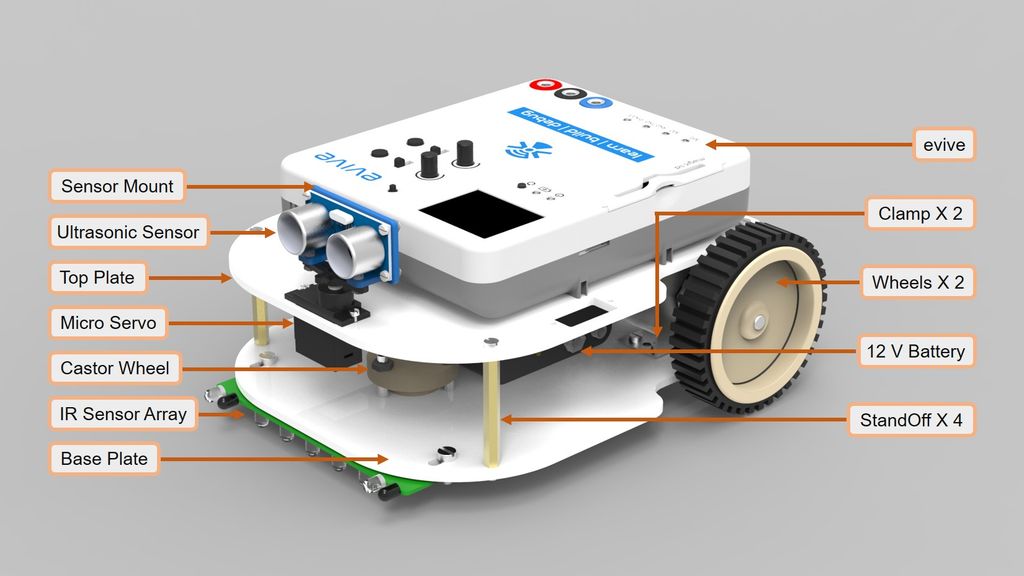
For your mobile manipulator, start with this chassis concept:
- Two equal-diameter driven wheels, one on the left and one on the right.
- One passive caster, positioned to enlarge the support area in the direction where the arm will most often reach.
- A low, wide rectangular chassis with room for a protected battery, control electronics, and arm pedestal.
- Arm pedestal centred left-to-right, so a left or right turn does not change the arm’s lateral balance dramatically.
- Battery mounted low, preferably under or near the arm base, with some room to shift it during stability tests.
- Forward obstacle sensor with a clear field of view, positioned where the arm and gripper do not block it.
- Wheel encoders marked as planned, even if you have not selected a motor yet. They are important for later wheel-speed control and odometry.
Top-view layout to sketch
Use this arrangement as a starting point, not a fixed final dimension:
                         FRONT

             Forward distance / obstacle sensor

                    Front support caster

              [ arm pedestal and J1 axis ]

       Left drive wheel              Right drive wheel

          Battery low in chassis, near arm mounting zone

       Motor drivers and microcontroller in protected enclosure

                          REAR
Draw the chassis outline around these components. Add three dashed contact points under the base: the left wheel, right wheel, and caster. Those points form the initial support polygon. Later, when the arm is extended with a payload, you will check whether the combined centre of mass remains inside that support region.
For now, do not claim the platform is stable merely because it has a wide chassis or a heavy battery. Stability depends on the arm pose, payload, wheel locations, caster location, base mass, and battery placement. Your sketch should make those factors visible so they can be tested.
The selected system concept
Record this as your current design decision:
| Subsystem | Provisional selection | Reason |
|---|---|---|
| Arm | Four-axis articulated arm: J1 yaw, J2 shoulder pitch, J3 elbow pitch, J4 wrist pitch | Enough control for a first pick-and-place arm while keeping mechanics and kinematics manageable |
| End effector | Servo-driven two-finger parallel gripper with removable fingers | Simple, printable, adaptable to objects with different geometry |
| Mobile base | Two-wheel differential drive with one caster | Compact, mechanically simple, compatible with encoder feedback and autonomous driving |
| Arm mount | Central laterally; low and close to chassis centre where packaging allows | Reduces unwanted side-to-side imbalance and bending load |
| Battery | Low in chassis and adjustable during integration | Helps stability and allows later ballast tuning |
| Sensors | Forward range sensing; wheel encoders; arm home switches planned | Supports obstacle-aware motion, repeatable homing, and later closed-loop control |
Create Concept Sheet 0.1
Create one page in your engineering build log. It can be a hand sketch, FreeCAD drawing, Shapr3D screenshot with annotations, or a tablet drawing. Keep it rough enough to revise.
Include these sections:
-
Arm side view
- J1 through J4 axes;
- approximate , , and wrist-to-tool length;
- home pose;
- maximum intended payload and target work area;
- tool centre point;
- actuator and cable-routing assumptions.
-
Arm top view
- J1 rotation range;
- chassis perimeter;
- areas the arm must not strike, such as the sensor, battery enclosure, or wheel guards.
-
Gripper detail
- jaw opening range;
- finger length;
- target object-size range;
- fingertip profile;
- attachment method for replaceable fingers.
-
Base top view
- wheel positions and approximate wheel diameter;
- caster location;
- arm pedestal;
- battery, controller, motor-driver, and sensor locations;
- approximate chassis length and width.
-
Assumptions and unresolved items
- “Shoulder actuator: TBD after torque estimate.”
- “Wheel motor and gear ratio: TBD after speed/torque calculation.”
- “Joint ranges: TBD after actuator selection and collision check.”
- “Battery position: TBD after static tipping test.”
- “Final gripper pad material: TBD after object trials.”
Use a revision record at the bottom:
| Revision | Change | Reason |
|---|---|---|
| 0.1 | Selected four-axis arm, parallel gripper, and differential-drive base | Establishes a practical first-build architecture |
This sheet is a design hypothesis. It is successful if it makes important uncertainties explicit, not if it looks final.
Wrap-up
You have now selected a coherent first physical concept:
- A four-axis articulated arm provides a manageable balance of reach, positioning, and controlled approach angle.
- A parallel-jaw gripper with replaceable fingertips supports practical experimentation with blocks, cylinders, and other common objects.
- A differential-drive chassis gives simple, controllable mobility while leaving room for batteries, sensors, and the arm pedestal.
- Your concept sketch must show motion axes, link lengths, the tool centre point, actuator locations, gripper geometry, wheel layout, and the base support points.
In the next lesson, you will convert this concept into an interface table. That will specify the mechanical, power, signal, and data connections among the arm, base, sensors, motor drivers, microcontroller, and Raspberry Pi.
Can't find a good explanation? Sign up and we'll make it for you
Sign up