
Hello again. You now have a saved main.tscn whose Main root is ready to hold the level. This lesson turns that empty scene into a compact shooting-range room: a visible floor and three walls, collision that will later stop the player, and a light so the geometry is readable.
The central idea is simple but essential: a mesh is what the player sees; a collision shape is what physics uses. We will keep both together under a StaticBody3D for each fixed piece of the room. By the end, your scene will be a reliable physical space for the first-person player and targets you build in later modules.
Plan the room before placing nodes
Godot measures 3D distances in meters: one engine unit is one meter. The axes are:
- X: left and right
- Y: up and down
- Z: front and back
We will make a simple open-front range, with targets eventually placed toward the back wall. Its floor will be meters wide and meters deep. The floor surface will sit at , while the collision box itself is a thin slab centered slightly below that surface.
Introduction to 3D — Godot Engine (stable) documentation in English
Read this official Godot documentation section to orient yourself in the 3D editor. It establishes the scale and axis conventions behind the room dimensions below.
In the “Coordinate system” section, read from the metric scale and axes. Then continue into “Space and manipulation gizmos” through the gizmo controls. Notice that red, green, and blue represent X, Y, and Z respectively; use the Inspector for exact values when building this first room.
Here is the scene-tree layout we are aiming for:
Main (Node3D)
├─ Ground (StaticBody3D)
│  ├─ CollisionShape3D
│  └─ MeshInstance3D
├─ BackWall (StaticBody3D)
│  ├─ CollisionShape3D
│  └─ MeshInstance3D
├─ LeftWall (StaticBody3D)
│  ├─ CollisionShape3D
│  └─ MeshInstance3D
├─ RightWall (StaticBody3D)
│  ├─ CollisionShape3D
│  └─ MeshInstance3D
└─ RangeLight (DirectionalLight3D)
There is deliberately no ceiling or front wall. That keeps the editor view open while still giving the future player floor collision and boundaries on the sides and back.
The visible object and the physical object are different
A MeshInstance3D displays geometry. A BoxMesh is an inexpensive primitive mesh that works well for block-shaped floors and walls. It looks solid in the viewport, but it has no physical effect by itself. A player could fall straight through it.
A StaticBody3D represents an object that does not move under physics simulation: a floor, wall, or fixed piece of scenery. It needs a CollisionShape3D child, and that child needs a shape resource, such as BoxShape3D. The shape is invisible when the game runs, but it is the boundary physics actually tests.
For this room, the visible BoxMesh and invisible BoxShape3D should have the same size and share the same parent. That alignment avoids the frustrating result where a character appears to touch a wall yet is blocked before reaching it, or seems partly inside the wall before collision occurs.

Build the floor: one complete visual-and-physical unit
Select Main in the Scene dock. Add a child node of type StaticBody3D and rename it Ground. With Ground selected, add these two children:
CollisionShape3DMeshInstance3D
The order does not affect physics, but keeping collision first and visual geometry second makes the tree easier to scan.
Select CollisionShape3D. In the Inspector, find Shape, click <empty>, and choose New BoxShape3D. Click the newly created BoxShape3D resource to expand it, then set Size to:
This creates a -meter-wide, -meter-deep slab only meters thick.
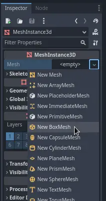
Next select MeshInstance3D. In the Inspector, find Mesh, click <empty>, and choose New BoxMesh. Expand the new BoxMesh resource and give it the exact same size:
Finally, select the parent node, Ground, and set its Position in the Inspector to:
Because the slab is meters thick and its center is at , its top face lies precisely at . This is a clean convention: later, you can place the player so its feet begin on the surface.
Setting up the game area — Godot Engine (stable) documentation in English
This official Godot first-3D-game guide demonstrates the exact node relationship used for the floor: StaticBody3D contains a CollisionShape3D for physics and a MeshInstance3D for visible geometry. It also introduces the directional light we will use after creating the walls.
In “Setting up the playable area,” begin at the floor construction walkthrough. Follow its Inspector steps, but use this lesson’s 20,\ 0.2,\ 16 dimensions rather than the guide’s much larger ground. Then, in the later portion of the same section, read from positioning the ground and adding light. The guide uses a 2-meter-thick floor moved down 1 meter; our thinner floor is centered at Y = -0.1 for the same reason: its top surface stays at Y = 0.
At this stage, look at the Scene dock rather than only at the viewport. The correct relationship is:
Ground (StaticBody3D)
├─ CollisionShape3D  — BoxShape3D, size (20, 0.2, 16)
└─ MeshInstance3D    — BoxMesh, size (20, 0.2, 16)
A warning icon beside CollisionShape3D means its Shape property is still empty. Do not ignore that warning: an empty CollisionShape3D does not provide collision.
Add three walls with matching boxes
Each wall follows the exact same pattern as Ground: a StaticBody3D parent containing one CollisionShape3D with a BoxShape3D, plus one MeshInstance3D with a BoxMesh.
Create the three wall parent nodes as direct children of Main:
BackWallLeftWallRightWall
For each one, add a CollisionShape3D and a MeshInstance3D, then create a BoxShape3D and BoxMesh. For a given wall, set both resources to the same Size. Set the parent StaticBody3D to the listed Position.
| Parent node | BoxShape3D and BoxMesh size | Parent position | Purpose |
|---|---|---|---|
BackWall | Stops the player at the far end of the range | ||
LeftWall | Blocks the left edge | ||
RightWall | Blocks the right edge |
These values are arranged carefully:
- The floor extends from to , and from to .
- Side walls centered at and sit on the floor’s left and right boundaries.
- The back wall centered at closes the far edge.
- Each wall is meters high and centered at , so its bottom is at , exactly on the floor.
For a new developer, typing these values into the Inspector is usually safer than dragging gizmos freely. The gizmos are excellent for quick placement, but an exact box room makes errors easy to diagnose. If you do use them, press W for move mode and remember that green is the Y axis.
Do not scale the StaticBody3D parent to create the wall proportions. Instead, change the size of both child resources. This keeps the visual mesh and collision shape explicitly matched. The next lesson will examine transforms and scaling more closely; for now, direct resource sizes are the least surprising method.
A common shortcut is to duplicate Ground and reshape it into a wall. This can be useful, but be cautious: duplicated nodes may initially share the same mesh or shape resource. Editing a shared resource can unexpectedly change more than one room piece. Creating each BoxMesh and BoxShape3D deliberately is slower by a few clicks but makes the relationship clear.
Light the range
Without a light source, a 3D scene can be much darker at runtime than it appears in the editor’s preview. Add a child of Main called RangeLight with type DirectionalLight3D.
A directional light behaves like a sun: its rotation determines the direction of illumination. Its location does not meaningfully act like the position of a lamp. For this small first room, use it as a simple overhead key light:
- Select
RangeLight. - In the Inspector’s Transform section, set its Rotation Degrees X to about
-45. - Enable Shadow in the light’s properties.
- Adjust the X rotation slightly if the room is too dark or the shadows point in an unhelpful direction.
A real indoor range might use several OmniLight3D or SpotLight3D nodes as ceiling fixtures. We are using a single directional light now because it illuminates the complete room with minimal setup and keeps the scene lightweight for eventual browser deployment.
Notice one subtle editor/runtime distinction: the editor can show preview lighting even when your scene does not contain light nodes. That preview is useful for building, but it is not a substitute for adding a real light to the scene.
Your completed tree should now look similar to this:
Main (Node3D)
├─ Ground (StaticBody3D)
│  ├─ CollisionShape3D
│  └─ MeshInstance3D
├─ BackWall (StaticBody3D)
│  ├─ CollisionShape3D
│  └─ MeshInstance3D
├─ LeftWall (StaticBody3D)
│  ├─ CollisionShape3D
│  └─ MeshInstance3D
├─ RightWall (StaticBody3D)
│  ├─ CollisionShape3D
│  └─ MeshInstance3D
└─ RangeLight (DirectionalLight3D)
Save with Ctrl+S or Cmd+S. You do not need to run the scene yet: it still has no Camera3D, so there is no player view. The next module will add that camera as part of the player scene.
Check the room structurally
Before moving on, inspect each fixed room piece using this short checklist:
- Its parent is a
StaticBody3D, not merely aNode3DorMeshInstance3D. - It has one
CollisionShape3Dchild with a non-emptyBoxShape3D. - It has one
MeshInstance3Dchild with a non-emptyBoxMesh. - The
BoxShape3DandBoxMeshuse identical dimensions. - The parent node has the intended position.
RangeLightis a child ofMain, has shadows enabled, and is rotated to cast light downward.
If the room looks correct but the eventual player passes through a surface, inspect the collision branch first. If collision works but no geometry appears, inspect the mesh branch. Separating these responsibilities is precisely why the node structure is useful.
Key takeaways
You have constructed the physical shell of a shooting range:
StaticBody3Drepresents room geometry that stays fixed.CollisionShape3DplusBoxShape3Dmakes that geometry solid to physics.MeshInstance3DplusBoxMeshmakes it visible.- Matching mesh and collision dimensions keeps what players see aligned with what blocks them.
- A
DirectionalLight3Dprovides real scene illumination; rotating it changes the direction of its light and shadows.
Next, you will use local and global transforms to position, rotate, and resize 3D objects with more confidence. That will make the parent-child spatial behavior in this room—especially moving a parent and its children—much easier to reason about.
Can't find a good explanation? Sign up and we'll make it for you
Sign up