
Hello! Welcome to your fifth lesson in Medical Instrumentation.
In our last session, we learned how to use active filters to isolate the specific frequency bands of our biomedical signals, a crucial step for cleaning up data. However, we noted that filtering doesn't solve the problem of noise that falls within our desired frequency band, especially pervasive noise like 50/60 Hz hum from power lines.
Today's lesson addresses this challenge head-on, focusing on the learning outcome: Calculate the Common-Mode Rejection Ratio (CMRR) and its importance in noise cancellation. We'll introduce the differential amplifier, the workhorse of biopotential measurement. You will learn how it distinguishes between the tiny physiological signal we want and the large, unwanted noise that contaminates it. For your work at Neuraease, understanding and leveraging a high CMRR is the single most important principle for acquiring clean, usable data from wearable sensors in noisy, real-world environments.
The Problem: Distinguishing Signal from Pervasive Noise
When we measure a biopotential like an EEG, we're interested in the tiny voltage difference between two points on the scalp. This is our differential-mode signal. However, the human body acts like an antenna, picking up electromagnetic interference from the environment, most commonly 50 or 60 Hz hum from AC power lines. This noise appears almost identically, or "in common," at both electrodes. This is our common-mode signal.
The problem is that the common-mode noise can be thousands of times larger than the differential-mode signal we want to measure. A single-ended amplifier, as we've used so far, would amplify both, completely burying the EEG signal.
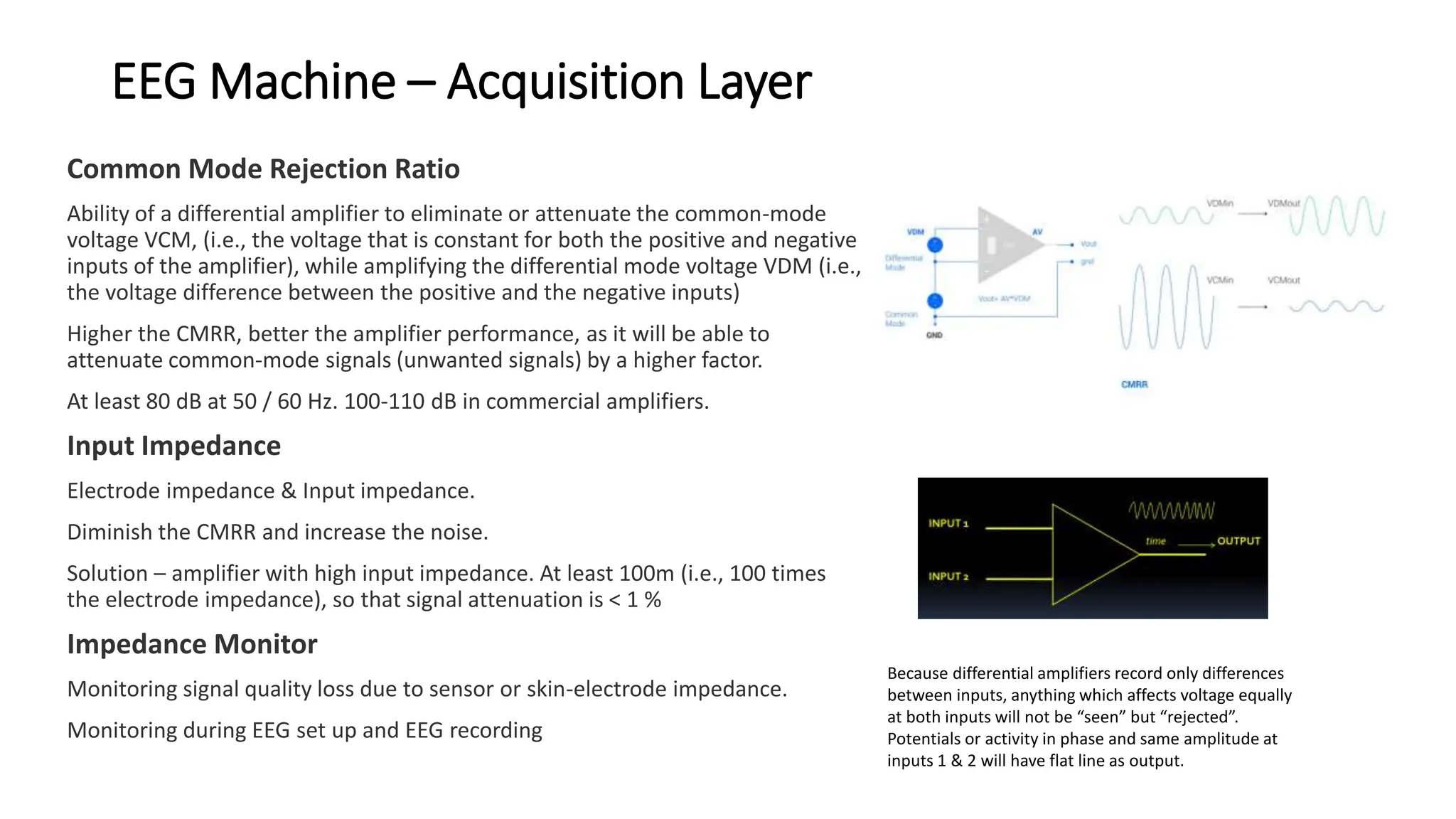
To get a more formal understanding of these signal types and where they come from, the following video provides a clear introduction.
Op-Amp: CMRR (Common Mode Rejection Ratio) Explained (with example)
The video 'Op-Amp: CMRR Explained' by ALL ABOUT ELECTRONICS provides a great foundation. It defines the common-mode configuration and identifies the most frequent sources of this unwanted noise.
Please watch from the beginning to 02:47. Focus on understanding the difference between how an ideal amplifier should behave with common inputs versus what happens in reality.
The Solution: Common-Mode Rejection Ratio (CMRR)
As the video introduced, a differential amplifier is designed to solve this exact problem. Its goal is to provide high gain for the differential-mode signal () and very low (ideally zero) gain for the common-mode signal ().
The Common-Mode Rejection Ratio (CMRR) is the figure of merit that quantifies how well an amplifier achieves this goal. It's the ratio of the differential gain to the common-mode gain.
Because this ratio is often very large, it is almost always expressed in decibels (dB):
A higher CMRR is always better. For biomedical applications like EEG or ECG, a CMRR of 80 dB to 120 dB is typically required.
- An 80 dB CMRR means is 10,000 times larger than .
- A 120 dB CMRR means is 1,000,000 times larger than .
This means that even if a 1V common-mode noise signal is present, the amplifier treats it as if it were a 100 µV (at 80 dB) or 1 µV (at 120 dB) signal at the input, effectively "rejecting" it.
Calculating the Impact of CMRR
Now, let's address the core of today's learning outcome: calculating the effect of CMRR. The total output of a real-world differential amplifier is the sum of the amplified differential signal and the amplified (and unwanted) common-mode signal.
where is the differential input voltage and is the common-mode input voltage.
The most common task is to determine the unwanted portion of your output signal caused by common-mode noise. We can rearrange the CMRR formula to find the output error.
To see a practical example of this calculation, please watch the next segment of the video from ALL ABOUT ELECTRONICS.
Op-Amp: CMRR (Common Mode Rejection Ratio) Explained (with example)
This part of the video walks through a step-by-step example, calculating the differential and common-mode output voltages for an amplifier with a given CMRR. This directly demonstrates how to apply the formulas.
Watch from 02:47 to 09:08. Follow the calculation of how a 90 dB CMRR is used to determine the final common-mode output voltage. Notice how small the final noise output is compared to the amplified signal.
Test your understanding!
You're designing an EEG front-end for your Neuraease wearable.
- The target EEG signal () is 50 µV.
- You expect to pick up 1 V of 60 Hz common-mode noise ().
- Your differential amplifier has a gain () of 1000 (60 dB).
- The amplifier's CMRR is 100 dB.
- What is the desired output voltage from the amplified EEG signal?
- What is the common-mode gain () of the amplifier?
- What is the magnitude of the unwanted 60 Hz noise at the output?
- What is the signal-to-noise ratio (SNR) at the output, in dB?
Show answer
-
Desired Signal Output:
-
Common-Mode Gain: First, we use the CMRR formula.
-
Unwanted Noise Output:
-
Output SNR:
In dB:
While we've recovered the signal, a 14 dB SNR shows there's still significant noise. This highlights why designers push for even higher CMRR and use additional filtering.
The Practical Solution: The Instrumentation Amplifier
So, how do we build an amplifier with a high CMRR? You might think we can just use one op-amp with a few resistors in a differential configuration. However, this approach has two major flaws:
- The input impedance is determined by the input resistors, which can be too low and load the delicate biopotential source.
- The CMRR becomes critically dependent on the resistors being perfectly matched. A tiny 1% mismatch can drop the CMRR to around 40 dB—completely inadequate for our needs.
To see a detailed analysis of this limitation and the superior solution, the next video is essential.
ECE 203 - Lecture 8 - Instrumentation Amplifiers I
In this lecture from ECE 203 by Prof. Patrick Mercier, you'll see the quantitative failure of a simple differential amplifier and the brilliance of the 'Three-Op-Amp Instrumentation Amplifier' architecture that solves these problems.
Watch the two key segments: The Problem (27:43 - 33:40): See how a 1% resistor mismatch in a simple differential amplifier results in a poor CMRR of only 68 dB, which is shown to be insufficient. The Solution (33:40 - 41:01): Understand how the three-op-amp topology achieves a very high CMRR (109 dB in the example) by using a high-gain differential input stage with unity common-mode gain. This is the core principle behind nearly all high-performance biomedical front-ends.
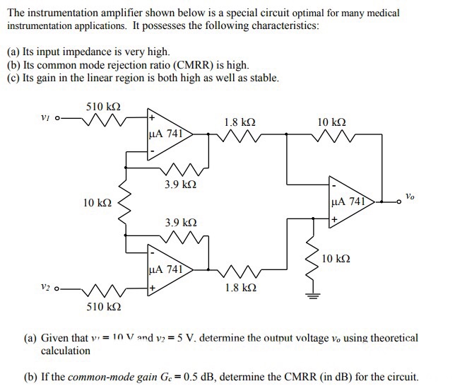
The circuit Prof. Mercier introduces, the Instrumentation Amplifier (In-Amp), is the gold standard for biopotential measurements precisely because it is architected for:
- Very High Input Impedance: The inputs go directly into the non-inverting terminals of op-amps, preventing any loading of the signal source.
- Very High CMRR: The two-stage design effectively separates differential amplification from common-mode rejection, overcoming the resistor matching problem.
- Easily Adjustable Gain: The gain is typically set by a single external resistor, .
Conclusion
Today we've uncovered the secret to measuring tiny signals in a world full of electrical noise. By understanding and applying the concept of Common-Mode Rejection, we can design front-ends that are exquisitely sensitive to the physiological signals we want, while remaining robustly insensitive to the interference we don't.
Key Takeaways:
- Biomedical measurements involve a small differential-mode signal (the one we want) superimposed on a large common-mode signal (noise).
- CMRR is the ratio of differential gain to common-mode gain () and quantifies an amplifier's ability to reject common-mode noise. It's usually expressed in dB.
- A high CMRR (>80 dB) is critical for extracting clean biopotentials.
- The Instrumentation Amplifier (typically a three-op-amp topology) is the standard circuit used to achieve high CMRR and high input impedance simultaneously.
Preview of the Next Lesson:
We now have a complete conceptual toolkit for a biopotential amplifier: it has high gain, high input impedance, is filtered to the correct frequency band, and has a high CMRR. But where does the signal itself come from? In the next lesson, we will move from electronics to physiology and address the learning outcome: Explain the ionic basis of resting and action potentials in excitable cells (neurons, muscle cells). This will form the biological foundation for understanding how signals like EEG, ECG, and EMG are generated in the first place.
Can't find a good explanation? Sign up and we'll make it for you
Sign up