
Hello! Welcome to your fourth lesson in Medical Instrumentation.
In our last session, we refreshed the fundamentals of operational amplifiers, learning how to use them to create amplifiers with specific gain. We concluded that while we can now make a weak biosignal much stronger, we are still amplifying both the signal and the noise.
Today, we will tackle that problem head-on. This lesson is dedicated to filtering, addressing the learning outcome: Apply active and passive filter concepts to design for specific biomedical frequency bands. We'll explore how to build circuits that selectively pass the frequencies containing our valuable physiological data while rejecting noise and artifacts. For your work at Neuraease, this is a cornerstone skill. Properly filtering data from wearables is essential for everything from removing 60 Hz power-line hum to isolating the specific EEG frequency bands that correlate with cognitive states.
Why Filtering is Non-Negotiable in Biomedical Design
A raw signal from an electrode is rarely clean. It's often contaminated with high-frequency noise from muscle activity (EMG), low-frequency drift from electrode movement, and ubiquitous 50/60 Hz interference from electrical wiring.
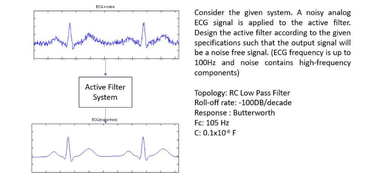
To see a practical walkthrough of this process, the following video shows the stages of building an ECG amplifier, highlighting the dramatic difference filtering makes.
The video 'Build an ECG Amplifier' by NickM provides a great narrative for why we need filtering. You'll see the raw, noisy signal straight from the amplifier and then the much cleaner signal after filtering.
Watch from 13:26 to 17:15. First, notice the frequency content of the raw signal using the FFT (13:26 - 16:14). The presenter identifies the desired low-frequency heart signal, the DC drift, and the 60 Hz noise. Then, see the effect of adding high-pass and low-pass filters to clean up the signal and reveal the classic PQRST waveform (16:14 - 17:15).
The Fundamental Filter Types
As the video demonstrated, we use different types of filters to target different parts of the frequency spectrum. The most comprehensive way to understand these is to start with their ideal characteristics.
Basic Introduction to Filters - Active, Passive, and Switched ...
This application note from Texas Instruments, 'A Basic Introduction to Filters', is an excellent reference for filter theory. We'll use it to define the basic filter types.
Please read section 1.2, 'The Basic Filter Types'. It covers Low-Pass, High-Pass, Bandpass, and Notch filters. Focus on understanding the shape of their ideal frequency response curves.
Here's how these filter types map directly to challenges in biomedical instrumentation:
- Low-Pass Filter (LPF): Passes low frequencies, blocks high frequencies.
- Application: Removing high-frequency noise, like muscle (EMG) artifacts from an ECG or EEG signal.
- High-Pass Filter (HPF): Passes high frequencies, blocks low frequencies.
- Application: Removing slow baseline "wander" or DC drift caused by electrode movement or changes in skin potential.
- Band-Pass Filter (BPF): Passes a specific band of frequencies.
- Application: Isolating a specific EEG rhythm, such as Alpha waves (8-13 Hz) to detect a state of relaxation, or Beta waves (13-30 Hz) for concentration. This is highly relevant for your work at Neuraease.
- Notch (or Band-Reject) Filter: Blocks a very narrow band of frequencies.
- Application: Specifically removing 50 Hz or 60 Hz power-line noise, which is one of the most common and disruptive sources of interference in bio-signal acquisition.
Passive vs. Active Filters
Filters can be built with passive components (resistors, capacitors, inductors) alone, or they can incorporate active components like op-amps.
- Passive Filters: Simple RC, RL, or RLC circuits.
- Pros: Simple, require no power.
- Cons: Can cause signal attenuation (insertion loss), have low input impedance and high output impedance (which leads to loading issues when connecting stages), and require inductors for higher performance, which are bulky, expensive, and non-ideal.
- Active Filters: Use op-amps along with resistors and capacitors.
- Pros: Can provide gain, have high input and low output impedance (ideal for cascading), and avoid the need for inductors. This makes them perfect for integration into compact, low-power instrumentation.
- Cons: Limited by the op-amp's bandwidth and require a power source.
Given the advantages for amplification and impedance matching we discussed in the last lesson, active filters are the standard choice for signal conditioning in modern biomedical devices. The TI document you just read has a great summary of this comparison in Section 2.4, which you can use for future reference.
Designing First-Order Active Filters
Let's apply these concepts to design the simplest active filters. A "first-order" filter uses a single reactive component (a capacitor in our case) to shape the frequency response. This results in a roll-off slope of -20 dB/decade for a low-pass filter or +20 dB/decade for a high-pass filter. The "Butterworth" characteristic mentioned below simply refers to a type of filter designed to have the flattest possible passband, making it a great general-purpose choice.
The following resource provides clear, step-by-step analysis and design procedures.
These 'LECTURE NOTES' from MRCET provide a straightforward approach to designing first-order active filters.
Please read the sections 'First order Low pass Butterworth Filter' and 'First Order High Pass Butterworth Filter'. Focus on the circuit diagrams, the frequency response graphs, and the simple design steps provided for each.
Key Design Equations
From that reading, here are the essential takeaways for designing first-order active filters using a non-inverting op-amp configuration:
1. Active Low-Pass Filter
- Circuit: An RC network precedes the non-inverting input of the op-amp.
- Intuition: At low frequencies, the capacitor acts as an open circuit, and the signal passes to the op-amp. At high frequencies, the capacitor's impedance drops, shunting the signal to ground.
- Cutoff Frequency (): This is the frequency where the signal power is halved (-3 dB).
- Gain (in the passband): Determined by the op-amp's feedback resistors, same as a standard non-inverting amplifier.
2. Active High-Pass Filter
- Circuit: The resistor and capacitor from the low-pass filter are swapped.
- Intuition: At low frequencies (and DC), the capacitor blocks the signal. At high frequencies, it acts like a short, allowing the signal to pass to the op-amp.
- Cutoff Frequency ():
- Gain (in the passband):
Higher-Order Filters and Response Characteristics
A first-order filter's roll-off of -20 dB/decade is often too gradual. If you have strong noise close to your signal's frequency, you need a "sharper" filter. This is achieved with higher-order filters, which are typically created by cascading first and second-order stages. A second-order filter rolls off at -40 dB/decade, a third-order at -60 dB/decade, and so on.
When designing higher-order filters, you must also choose a response type, which involves trade-offs between passband flatness, roll-off steepness, and phase distortion.
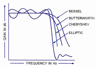
The main types you'll encounter are:
- Butterworth: The best general-purpose choice. It offers the flattest possible passband with no ripple, leading to a very predictable gain for all frequencies you want to keep.
- Chebyshev: Steeper roll-off than Butterworth, but at the cost of "ripple" (small gain variations) in the passband.
- Bessel: The most gradual roll-off, but it has a linear phase response. This is critical when the shape of the signal in time is important, as it prevents waveform distortion. This is vital for analyzing things like Event-Related Potentials (ERPs) in EEG data.
- Elliptic: The steepest roll-off possible, but has ripple in both the passband and stopband. Use this when you need to aggressively separate frequencies and can tolerate the ripple.
A common way to build second-order active filters is with the Sallen-Key topology. This video gives a great introduction to the design process.
How to design active filters using Sallen Key circuits (2 - Active Filters)
The video 'How to design active filters using Sallen Key circuits' by Aaron Danner provides a concise tutorial on this widely used topology for second-order filters.
Watch the first 4 minutes (00:00 - 04:09). You don't need to memorize the equations, but focus on the overall design procedure: you specify the order and cutoff frequency, choose a capacitor value, calculate the resistor value, and then set the gain (K) based on tables for the desired response (e.g., Butterworth).
Test your understanding!
You are designing a wearable device for Neuraease to monitor stress by analyzing heart rate. The PPG signal you acquire is solid, but it's contaminated by high-frequency noise from ambient light flicker and muscle twitches, starting at around 10 Hz. The useful information for heart rate is all below 5 Hz.
You need to design a simple active low-pass filter to clean up the signal before calculating the heart rate.
- What filter type and order would you start with for this application?
- Let's set the cutoff frequency to 8 Hz to be safe. If you choose a standard capacitor value of 0.1 µF, what value of resistor would you need?
- If you want the filter to also provide a gain of 2, what values could you choose for the feedback resistors and ?
Show answer
-
A first-order active low-pass Butterworth filter is a great starting point. It's simple to design and its "maximally flat" passband ensures that all the frequencies below 5 Hz are treated with uniform gain, without distortion.
-
Using the cutoff frequency formula:
We rearrange to solve for R:
A standard resistor value close to this is 20 kΩ. -
For a non-inverting amplifier, the gain is . We want a gain of 2.
So, we just need to choose two equal resistors. A common and good choice would be and .
Conclusion
Today, we've transformed our amplifier from a simple gain block into an intelligent signal conditioner. By adding just a few components, we can now create circuits that amplify only the frequencies we care about, a crucial step in designing any real-world biomedical instrument.
Key Takeaways:
- Filters are essential for rejecting noise (e.g., 60 Hz hum, muscle artifacts) and isolating specific frequency bands (e.g., EEG rhythms).
- The four main types are Low-Pass, High-Pass, Band-Pass, and Notch filters.
- Active filters (using op-amps) are preferred in biomedical design for their ability to provide gain and for their excellent impedance characteristics.
- The cutoff frequency of a first-order RC filter is determined by .
- For sharper filtering, higher-order filters are used. The choice of Butterworth, Chebyshev, or Bessel response involves trade-offs between passband flatness, roll-off steepness, and phase distortion.
Preview of the Next Lesson:
We now have amplification and filtering. However, much of the noise in a biomedical setting (like 60 Hz hum) appears equally on all electrodes. Our current single-ended amplifiers would amplify this noise just as much as our signal. In the next lesson, we will introduce the differential amplifier and the concept of Common-Mode Rejection Ratio (CMRR), a figure of merit that describes how well an amplifier rejects this common noise. This will lead us directly to the instrumentation amplifier, the gold standard front-end for biopotential measurements.
Can't find a good explanation? Sign up and we'll make it for you
Sign up