
Hello! Welcome to your next lesson.
In our last session, we mapped out the brain's electrical landscape, learning how to place electrodes using the 10-20 system and how to display the resulting data with different montages. We now have a solid framework for where to measure and how to look. Today, we're diving into the electronics to answer the crucial question: how do we build the machine that actually performs the measurement?
This lesson is designed to meet the learning outcome: Design an EEG acquisition system with appropriate specifications for amplification, filtering, and grounding.
This is a core topic where your ECE background will be a significant asset. For your university exams, you'll be expected to understand the architecture of such systems and justify your design choices. For your work at Neuraease, mastering these principles is fundamental to developing a high-quality wearable device. The quality of any data analysis or machine learning model is ultimately limited by the quality of the signal acquired at the front end.
1. The Big Picture: Block Diagram of an EEG Acquisition System
Before we dive into the details of each component, let's look at the overall signal chain. An EEG signal travels from the scalp through several critical stages before it can be analyzed.
To get a clear overview, let's examine the block diagram from a practical EEG circuit design paper.
The circuit design for extraction of electro encephalogram ...
This paper, 'The circuit design for extraction of electro encephalogram...', provides a clear block diagram of a complete EEG acquisition system. This will serve as our roadmap for today's lesson.
Please examine Figure 1 in the first section of the paper. This shows the path from the EEG signals at the electrodes, through pre-amplification, filtering, and post-amplification.
As you can see, a typical system consists of:
- Electrodes: The sensors that pick up the initial signal.
- Pre-amplification: The first and most critical amplification stage.
- Filtering: A series of filters to remove noise and unwanted frequencies.
- Post-amplification: Additional gain to match the signal level to the next stage.
- Analog-to-Digital Converter (ADC): Converts the analog signal into a digital format for the computer.
We will now design this system, block by block.
2. Defining the Design Specifications
A good design starts with clear targets. What performance characteristics are we aiming for? EEG signals are notoriously difficult to measure, so our specifications must be stringent.
The following reading provides an excellent summary of the key features and typical values for a modern EEG amplifier.
Main features of the EEG amplifier explained
The article 'Main features of the EEG amplifier explained' from Bitbrain gives a concise summary of the essential specifications for an EEG system. This will provide the target numbers for our design.
Read the introductory section and the summary list of 8 features. These numbers represent our design goals.
Based on this, our target specifications for a high-quality EEG acquisition system are:
- Input Impedance: > 100 MΩ
- Common Mode Rejection Ratio (CMRR): > 80 dB (ideally > 100 dB)
- Bandwidth: ~0.5 Hz to 70 Hz
- Input Referred Noise: < 1 µVrms
- Total Gain: High enough to bring a ~50 µV signal up to the ~1-5V range suitable for an ADC (e.g., a gain of 20,000 to 100,000).
Now, let's build a circuit that can meet these demanding requirements.
3. The Pre-Amplifier: The Heart of the System
The EEG signal is minuscule (10-100 µV) and buried in noise. The first amplifier stage (the pre-amplifier) is the most critical part of the entire system. Its job is to provide high gain to the tiny differential EEG signal while aggressively rejecting the large common-mode noise that contaminates it.
For this task, the standard solution is the Instrumentation Amplifier (IA). Let's take a deep dive into why this specific amplifier topology is so essential.
ECE 203 - Lecture 8 - Instrumentation Amplifiers I
This lecture, 'ECE 203 - Instrumentation Amplifiers I' by Prof. Patrick Mercier, is perfectly suited to your background. It explains the need for IAs in biopotential measurement from an electrical engineering perspective, highlighting their key advantages over simpler designs.
Please watch the following segments carefully: The Problem (1:18 - 9:16): This covers the characteristics of biopotential signals (like EEG) and outlines the general requirements for the amplifier. Pay close attention to the list of requirements (high input Z, high CMRR, etc.). The Importance of Input Impedance (15:13 - 22:34): This explains why high input impedance is non-negotiable, discussing both signal attenuation and the critical issue of common-mode to differential-mode conversion from electrode impedance mismatch. The Solution (22:34 - 38:00): This segment first shows why a simple single op-amp differential amplifier is insufficient due to poor CMRR with mismatched resistors, and then introduces the classic three-op-amp instrumentation amplifier as the solution that provides both high input impedance and excellent CMRR.
To summarize the key points from the video:
- High Input Impedance: Achieved because the signal inputs connect directly to the non-inverting inputs of the first-stage op-amps. This prevents the amplifier from loading the high-impedance electrode-skin interface, ensuring the tiny EEG signal is not attenuated before it's even amplified.
- High CMRR: The two-stage structure is key. The first stage provides high differential gain but only unity gain for common-mode signals. The second stage (the differential amplifier) then rejects this common-mode signal. The overall CMRR is boosted significantly, allowing the circuit to ignore noise that appears on both electrodes simultaneously.
- High, Settable Gain: The gain of the IA is typically set by a single external resistor (), making it easy to adjust without disturbing the intricate balance of the differential stages. For the classic three-op-amp IA, the gain of the first stage is given by: where are the feedback resistors in the first stage.
Test your understanding!
An EEG system is being designed with a three-op-amp instrumentation amplifier. The electrode-skin impedance is estimated to be around 50 kΩ. Why would a simple differential amplifier with 10 kΩ input resistors be a poor choice for the pre-amplifier stage, even if the resistors were perfectly matched?
Show answer
A simple differential amplifier's input impedance is determined by its input resistors (10 kΩ in this case). This low input impedance forms a voltage divider with the high electrode impedance (50 kΩ). A significant portion of the already tiny EEG signal would be dropped across the electrode impedance, leading to severe signal attenuation before amplification. The instrumentation amplifier avoids this by presenting a much higher input impedance (in the GΩ range).
4. Grounding and Common-Mode Rejection
We've established that an IA has high CMRR, but we can do even better. The largest source of noise is often 50/60 Hz powerline interference that couples capacitively to the entire body, appearing as a large common-mode signal. We can actively cancel this noise using a clever circuit known as the Driven Right Leg (DRL) circuit.
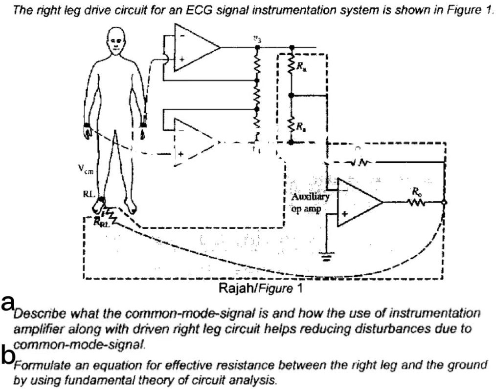
The DRL circuit serves two critical purposes:
- Establishes a DC Bias Path: The high-impedance inputs of the IA need a DC path to ground for proper biasing. The DRL provides this reference potential for the patient's body relative to the amplifier's ground.
- Active Noise Cancellation: It senses the common-mode voltage present at the IA inputs, inverts it, and feeds it back to the body. This negative feedback loop actively drives the common-mode voltage on the body towards zero, effectively canceling the 50/60 Hz interference before it even reaches the main amplifier.
For a detailed walkthrough of how this works, let's return to the ECE lecture.
ECE 203 - Lecture 8 - Instrumentation Amplifiers I
This segment of the lecture explains the Driven Right Leg circuit, a crucial component for both noise reduction and patient safety.
Watch the segment from 41:01 to 48:55. Focus on the two main benefits: setting the common-mode range of the amplifier and actively canceling interference. Also, note the function of the series resistor (R_O) in the DRL output for patient safety.
The safety resistor mentioned in the video is non-negotiable. It limits the current that could flow into the patient in the event of a circuit fault, preventing electric shock.
5. Filtering Out Unwanted Signals
Even with a great amplifier and DRL, filtering is essential to isolate the desired EEG frequency band. Our target bandwidth is roughly 0.5 Hz to 70 Hz. This requires both a high-pass and a low-pass filter.
High-Pass Filter: Removing DC Offset
The electrode-skin interface generates a large, slow-drifting DC offset voltage (up to several hundred millivolts). If we amplify this DC offset by a factor of 100,000, it will instantly saturate the amplifier's output.
The solution is AC coupling: placing capacitors in series with the inputs. This blocks the DC component while letting the AC signal (our EEG) pass. This capacitor, combined with the amplifier's input impedance, forms a high-pass filter.
The cutoff frequency is given by . For EEG, we need to set this cutoff very low, around 0.1-0.5 Hz, to avoid filtering out slow brain potentials. This requires very large resistance or capacitance values.
This paper shows a practical implementation of such a filter.
The circuit design for extraction of electro encephalogram ...
Let's look at a practical high-pass filter design from the circuit paper.
Read the short section 'The high pass-filtration.' The authors set the cut-off frequency to 0.3Hz to preserve the low-frequency components of the EEG signal.
Low-Pass and Notch Filters
- Low-Pass Filter: This is needed to remove high-frequency noise, primarily muscle artifacts (EMG) which can contaminate the EEG. It also serves as an anti-aliasing filter before the ADC, a concept you'll remember from your signal processing studies. A typical cutoff frequency is ~70-100 Hz.
- Notch Filter: While the DRL and high CMRR of the IA suppress most powerline noise, a dedicated notch (or band-stop) filter is often included to sharply attenuate any remaining 50 or 60 Hz interference.
The paper provides concrete examples of these stages.
The circuit design for extraction of electro encephalogram ...
The same paper shows how the low-pass and notch filter stages are implemented to complete the signal conditioning chain.
Briefly review the sections 'The 50 Hz band-pass filter' (note: this is a typo in the paper, it's a band-stop/notch filter), 'The Low-pass filtration,' and 'The post-stage amplification.' This shows how all the pieces fit together to shape the signal and provide the final gain.
Conclusion
We have now designed a complete, multi-stage EEG acquisition system from the ground up, specifying each critical component based on the unique challenges of measuring brain signals.
Key Takeaways:
- System Architecture: An EEG system is a cascade of a pre-amplifier, filters, and a main amplifier to prepare the signal for digitization.
- Amplification: The three-op-amp instrumentation amplifier is the industry standard, providing the necessary high gain, extremely high input impedance, and high CMRR.
- Grounding & Noise Rejection: The Driven Right Leg (DRL) circuit is a key innovation that provides a stable bias for the amplifier and actively cancels common-mode noise like 50/60 Hz interference, while a series resistor ensures patient safety.
- Filtering: A specific filter chain is required:
- High-Pass ( Hz): Removes DC electrode offset via AC coupling.
- Low-Pass ( Hz): Removes high-frequency noise (EMG) and prevents aliasing.
- Notch ( Hz): Removes residual powerline interference.
These design principles are universal. Whether you are analyzing a commercial EEG system for an exam or designing a low-power, miniaturized version for your Neuraease wearable, the core challenges of high input impedance, common-mode rejection, and appropriate filtering remain the same.
Preview of the Next Lesson:
Our hardware is now designed to capture the best possible signal. However, some noise and artifacts will always leak through. In our next lesson, we will shift from hardware to software and learn to identify and apply techniques to mitigate common EEG artifacts like eye blinks (EOG), muscle tension (EMG), and powerline noise using signal processing methods.
Can't find a good explanation? Sign up and we'll make it for you
Sign up