
Hello! Welcome to your next lesson in our Medical Instrumentation course.
In our last session, we explored the neurophysiological origins of the EEG signal, understanding that it represents the summed electrical activity of millions of synchronized pyramidal neurons. We now know what we are trying to measure. Today, we'll address the critical next step: how we systematically place our sensors and view the data they collect.
This lesson directly addresses the learning outcome: Explain the 10-20 international system for electrode placement and different montage types.
Mastering this is non-negotiable for anyone working with EEG. For your university exams, you'll need to know these standards by heart. For your work at Neuraease, this knowledge is the bedrock of reproducible research and development. The choice of electrode placement and display method (the montage) fundamentally shapes the data you analyze and the features you can extract for your machine learning models.
1. The 10-20 International System: A Universal Map for the Head
To compare EEG recordings across different people, different labs, and even different sessions with the same person, we need a standardized method for placing electrodes. The 10-20 International System is that standard. It's an ingenious method that uses proportional distances based on key anatomical landmarks, ensuring consistent placement regardless of head size or shape.
The Logic: Landmarks and Percentages
The system gets its name because the distances between adjacent electrodes are either 10% or 20% of the total distance between specific landmarks. The four primary landmarks are:
- Nasion: The point between the eyes, at the top of the nose.
- Inion: The bony bump at the back of the skull.
- Left and Right Preauricular Points: The small depressions just in front of each ear canal.
Measurements are taken between these points (front-to-back and side-to-side) and then divided into 10% and 20% intervals to mark the electrode locations.
To see this process in action, let's watch a short video that clearly explains the measurement and labeling conventions.
This clip from the 'Introduction to EEG' video by Dr. Jeremy Moeller provides a concise visual walkthrough of how the head is measured and how the 10-20 system's naming convention works.
Please watch from 00:36 to 02:53. Focus on the four anatomical landmarks and how the measurements are divided. Also, pay close attention to the logic behind the electrode labels (letters and numbers).
The Naming Convention (Nomenclature)
As the video explained, the naming system is logical and descriptive:
- Letters indicate the underlying brain lobe or region:
- Fp: Fronto-polar
- F: Frontal
- C: Central
- T: Temporal
- P: Parietal
- O: Occipital
- Numbers indicate the hemisphere:
- Odd numbers (1, 3, 5, 7) are on the left hemisphere.
- Even numbers (2, 4, 6, 8) are on the right hemisphere.
- The letter 'z' (for "zero") denotes an electrode on the midline.
Here is a classic diagram showing the complete 10-20 system layout.

For a quick reference and to reinforce these concepts, the following reading provides another clear summary.
EEG Montages and Technical Components
This section from LearningEEG.com, titled 'The 10-20 System,' offers a great textual summary of the system's purpose and naming convention. It also introduces a couple of extra electrodes you might encounter.
Please read the first section, 'The 10-20 System.' Note the clarification that F7/F8 electrodes, despite their 'F' label, are actually over the anterior temporal region.
It's also worth knowing that for high-density EEG (using 64, 128, or even 256 electrodes), extensions like the 10-10 system and 10-5 system exist. They simply fill in the gaps between the 10-20 locations, providing higher spatial resolution, which can be useful for advanced source localization techniques.
Test your understanding!
An EEG report mentions a focal spike observed maximally at electrode P3. Based on the 10-20 nomenclature, in which region and hemisphere of the brain did this activity occur?
Show answer
The activity occurred in the left parietal region. 'P' stands for Parietal, and the odd number '3' indicates the left hemisphere.
2. Montages: Viewing the Brain's Activity
Placing the electrodes is only the first step. A montage is the specific arrangement of electrode pairs that we display on the screen. Since EEG relies on differential amplifiers, we are always looking at the voltage difference between two points. A montage is essentially a curated list of these comparisons.
Think of it like setting up cameras at a sports event. You can have a wide-angle view, a close-up on a specific player, or a view from the sideline. Each view tells a different part of the story. Similarly, different montages are used to highlight different aspects of brain activity. There are two main families of montages: Bipolar and Referential.
3. Bipolar Montages
In a bipolar montage, each channel displays the voltage difference between two adjacent electrodes. These pairs are linked together to form chains.
The most common bipolar montage is the longitudinal bipolar or "double banana" montage. It consists of chains running from the front to the back of the head.
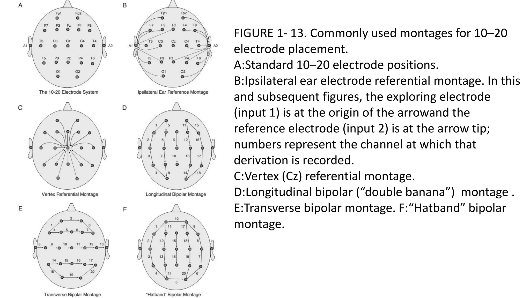
A key feature of bipolar montages is the phase reversal. This is a pattern that helps to localize the source of a signal. If an electrode is right over the peak of a negative discharge, the channels on either side of it will show deflections that "point" towards each other.
To get a solid grasp of how these chains are built and how to interpret them, the next reading is essential.
EEG Montages and Technical Components
The article 'EEG Montages and Technical Components' provides an excellent explanation of bipolar montages. It details the 'double banana' setup, the concept of phase reversals, and a practical issue called the 'end of chain phenomenon.'
Please read the sections 'Bipolar Montages I: Setup' and 'Bipolar Montage II: Types.' Focus on understanding how a tracing line is calculated and what a phase reversal looks like. Pay attention to the different types like circumferential and transverse montages and why they might be used.
As you read, bipolar montages are excellent for pinpointing the location of focal events. The main types to remember are:
- Longitudinal (e.g., Double Banana): Front-to-back chains. The workhorse for general EEG screening.
- Transverse: Side-to-side chains. Good for comparing activity between the left and right hemispheres.
- Circumferential: Electrodes linked in a circle around the head. Useful for getting around the "end of chain" problem, especially for activity in the frontal or occipital poles.
4. Referential Montages
In a referential montage, every channel displays the voltage difference between an active electrode on the scalp and a single, common reference point.
This makes interpretation more direct: an upward wave is negative, a downward wave is positive, and the channel with the largest wave is the one closest to the activity. There are no phase reversals.
The challenge lies in choosing a good reference. The ideal reference is electrically silent, but this is impossible to achieve in practice. The main types of references are:
-
Common Physical Reference: Using a single electrode, like one on the vertex (Cz), or on the earlobes (A1/A2). The problem is that if this reference electrode picks up any electrical activity (either brain activity or artifact), that activity will be "projected" into every single channel, contaminating the entire recording.
-
Average Reference: A mathematical reference where each electrode is compared to the average potential of all other electrodes. This is very common in digital EEG. While it often works well, it is susceptible to reference contamination.
The following video brilliantly explains these concepts, especially the problem of reference contamination, using a very intuitive analogy. It also introduces a more advanced technique, the Laplacian montage.
The 'EEG Montages' video by Dr. Jeremy Moeller is one of the best resources for understanding the practical differences between montages. It clearly explains referential montages and uses a fantastic analogy to illustrate reference contamination.
Please watch from 02:42 to 11:00. Pay special attention to the 'tall man' analogy for reference contamination (starting around 04:55). Also, note the description of the Laplacian montage, which is a technique to improve spatial focus.
As the video powerfully illustrates, a large, focal discharge can make the average potential of the whole head shift, creating the false appearance of activity in channels that are actually quiet. This is a critical point to understand when analyzing EEG data, especially with automated algorithms that might be fooled by such artifacts.
The Laplacian montage (or source derivation) is a clever solution that computes a local reference for each electrode based on its immediate neighbors. This makes it excellent for sharpening the focus on focal events and is highly resistant to contamination from distant sources.
Conclusion
Today, we've established the standardized framework for acquiring and viewing EEG signals. You now have the vocabulary and conceptual tools to understand how any EEG recording is set up.
Key Takeaways:
- The 10-20 System is the international standard for placing EEG electrodes, using proportional distances from anatomical landmarks to ensure consistency.
- A montage is a specific scheme for displaying the voltage differences between electrodes. There is no single "best" montage; the choice depends on the goal.
- Bipolar montages compare adjacent electrodes and are excellent for localizing focal events using phase reversals.
- Referential montages compare all electrodes to a common point (physical or mathematical). They are good for assessing voltage amplitude but can suffer from reference contamination.
- Modern digital EEG systems allow you to re-reference the data and switch between montages after the recording is complete, which is a powerful tool for analysis.
For your work at Neuraease, this means that when you are designing or using a wearable device, you must be precise about both electrode locations (e.g., "electrodes placed at Fp1 and Fp2") and the referencing scheme used for analysis (e.g., "data was re-referenced to the average of all channels"). This is fundamental for data integrity and for comparing your results to established research.
Preview of the Next Lesson:
We know what the signal is, where to place the electrodes, and how to display the data. The next step is to build the machine itself. In our next lesson, we will dive into the electronics and design an EEG acquisition system, specifying the requirements for amplification, filtering, and grounding to capture a clean, high-fidelity signal. This will be a great opportunity to apply your ECE background to a real-world biomedical challenge.
Can't find a good explanation? Sign up and we'll make it for you
Sign up