
Welcome back. In our last session, we conducted a Design for Assembly (DFA) review and identified several critical issues the ECO introduced to our BIW bracket assembly process, most notably regarding robotic weld gun access and fixture complexity. That analysis focused on the downstream effects of the change.
Today, we shift our focus upstream to the manufacturing process of the part itself: sheet metal stamping. An engineering change is never "free." Even a small geometric modification can have a ripple effect that results in thousands, or even millions, of dollars in tooling costs and weeks of production delays. Your responsibility as a lead engineer is to foresee these impacts.
Our objective is to identify potential stamping die modifications or risks resulting from the ECO. We will explore how to analyze a part change and translate it into a concrete assessment of tooling impact, cost, and risk.
1. The Stamping Die: A Complex Machine
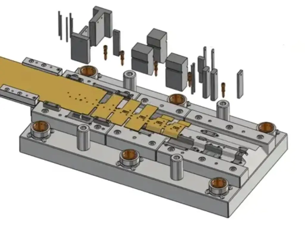
Before we can assess the impact of a change, we must first understand what we are changing. A progressive stamping die is not a simple tool; it's a highly complex, multi-station machine designed to perform a precise sequence of operations.
To visualize this complexity, let's look inside a real tool and die shop.
The Mind-Blowing Machines that Stamp Millions of Metal Parts - Smarter Every Day 288
This video, "The Mind-Blowing Machines that Stamp Millions of Metal Parts" from the Smarter Every Day channel, provides an excellent tour of a stamping and tooling facility.
Watch these segments to understand the nature of a progressive die: Die components: Pay close attention to the distinction between the top and bottom halves of the die and the concept of modular inserts made of hardened tool steel. Strip progression: Mark, the toolmaker, walks through how a flat strip of metal is progressively pierced, formed, and cut in a series of stations. This step-by-step transformation is the "process" we need to analyze. Die maintenance: This section is critical. It explains the difference between a modular die (with replaceable inserts) and a monolithic die. This distinction is fundamental to the cost and feasibility of any modification.
As you saw, a progressive die is a story told in steel. Each station advances the narrative, transforming a flat blank into a finished part. An ECO that changes the part's geometry forces us to rewrite parts of that story.
2. A Framework for Assessing Die Impact
When an ECO is released, your first call should be to the tooling engineer. They will lead the detailed analysis, but you must be able to anticipate the key questions and risks. Here is a framework for that analysis.
Step 1: Differentiate Between Process Failure and Die Design Error
Not all changes are equal. Some require minor tweaks; others require starting over. The article "Die Science" provides a crucial distinction.
Die Science: Recognizing the need for tooling changes
This article by Art Hedrick, a stamping expert, explains the two fundamental types of tooling issues. This framework is essential for categorizing the risk of an ECO.
Read the entire article, focusing on the definitions of: Process Design: The sequence of steps determined by the process engineer to make the part. Die Design: The mechanical means (the tool) to execute that process. Process Failure: The sequence of operations is fundamentally wrong for the desired geometry. The consequence is catastrophic and often requires a new die. Die Design Error: The process is correct, but the tool is not built robustly enough to execute it (e.g., insufficient force, wrong material). This can often be corrected with mechanical changes.
When evaluating an ECO, your first question must be: "Does this change invalidate our current manufacturing process?" If you change a part from a simple bend to a deep draw, you have a process failure. The old die is likely obsolete. This is the highest level of risk.
Step 2: Map Geometric Changes to Die Stations
If the change does not cause a fundamental process failure, you must then trace its impact station by station.
Consider our ECO, which adds a gusset to the L-bracket:
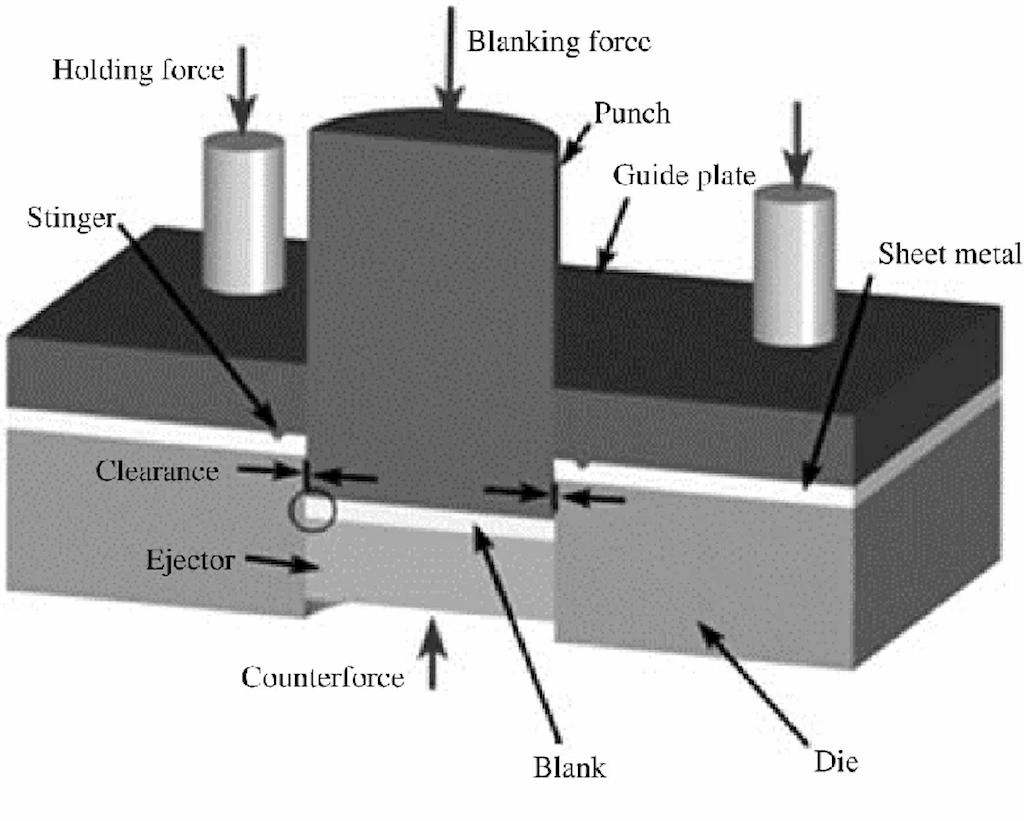
- Blanking/Piercing Stations: The flat pattern of the part has changed significantly to include the material for the gusset. This means the blanking punches that define the part's outer profile must be remade. Any piercing punches near the new feature may need to be relocated or changed.
- Forming Stations: The original die likely had a single station to create the 90-degree bend. The new gusset is a three-dimensional feature. It requires a new forming station. If the gusset is angled or has an undercut, it may require a cam-actuated slide—a complex and expensive mechanism that uses horizontal motion within the vertical press stroke.
- Trimming/Cut-off Stations: Since the final part shape is different, the station that cuts the finished part from the carrier strip must be modified or replaced.
Step 3: Identify Secondary Risks
Beyond the direct geometric changes, an ECO can introduce subtle but critical physical problems.
- Springback: High-Strength Steels (HSS), like the DP600 used for our bracket, have significant springback. The original die was compensated (over-bent) to account for this. Adding a stiffening gusset fundamentally changes the part's structural behavior. The original springback compensation is now incorrect, and the part will not form to the correct angle. The forming tools will need to be re-cut based on new trial-and-error or simulation data.
- Material Flow: The new gusset requires material to be drawn and stretched into a new shape. This can lead to unwanted thinning, stress concentrations, or even tearing if the process is not carefully developed. This might require changes to binder shapes or adding draw beads to control material flow—a non-trivial modification.
The paper "Integrated build: a new approach to building automotive bodies" discusses how some advanced manufacturers handle these risks. In Case Study 2, they intentionally build simple tools first and then empirically measure springback on production parts, modifying the dies afterward. This "Integrated Build" philosophy acknowledges that predicting these effects perfectly in software is extremely difficult. It highlights that die modification is often an expected part of the launch process, not a sign of failure.
3. Your Task: Analyze the Die Impact of the Bracket ECO
Let's apply this framework to our bracket assembly. You are presenting your analysis of the ECO to the program team.
Scenario: The ECO adds a triangular gusset to an existing L-bracket made from DP600 steel. The original die for the simple L-bracket is already built and in tryout.
-
Process Impact: Based on the "Die Science" article (LINK), why is adding the 3D gusset more likely a Process Failure for the original die, rather than a simple die design modification?
-
Die Station Impact: The original die for the L-bracket has 5 stations:
- Station 1: Pierce pilot holes
- Station 2: Trim part profile (blank)
- Station 3: Form 90-degree bend
- Station 4: Idle
- Station 5: Cut-off part from strip
The ECO integrates the gusset into the L-bracket stamping. Which station(s) are definitely obsolete, and what new type of forming operation/mechanism might be required that was not present before?
-
Springback Risk: The material is DP600 steel. The original L-bracket had a predictable 2-degree springback, which the die compensated for by forming the part to 88 degrees. Why does adding the stiffening gusset create a significant new risk related to the final angle of that main 90-degree bend?
-
Challenge Question (Cost & Lead Time): You're in a meeting with the Tooling Engineer. They tell you the existing die is a "monolithic" design from a low-cost supplier. Referring to the
SmarterEveryDayvideo's discussion on die construction and maintenance (LINK), what is the most significant implication you would immediately raise regarding the ECO's business case?
Click here for my analysis and suggested answers.
-
Process Impact: This is likely a Process Failure because the fundamental sequence of operations required to make the part has changed. A simple L-bracket is made with a "wiping" or "flanging" process. A part with an added 3D gusset likely requires a "drawing" or "stretch-forming" operation to shape the gusset without tearing or wrinkling the material. The original 5-station process is incapable of performing this new operation; therefore, the process itself is invalid for the new part geometry.
-
Die Station Impact:
- Obsolete Stations: Station 2 (Trim part profile) is obsolete because the flat pattern is completely different. Station 3 (Form 90-degree bend) is also obsolete because the forming punch/die for a simple bend cannot accommodate the new gusset geometry. Station 5 (Cut-off) is also obsolete due to the new part perimeter.
- New Operation/Mechanism: A new drawing station would be needed to form the gusset. Depending on the gusset's angle and shape relative to the press direction, a cam-actuated slide would likely be required to form features that are not vertical. This adds significant cost and complexity to the die.
-
Springback Risk: The gusset acts as a major stiffener. The original part's springback was determined by the simple L-section's stiffness. By adding the gusset, the part's resistance to bending and its tendency to spring back after forming are fundamentally altered. The original 2-degree compensation is no longer valid. The part may now spring back more or less, and the effect might not be uniform along the bend. This requires new analysis and physical rework of the forming steel, which is a costly, iterative process.
-
Challenge Question (Cost & Lead Time): The
SmarterEveryDayvideo emphasizes that high-quality dies are modular, built with replaceable inserts. A "monolithic" die is made from large, solid blocks of steel. The implication is that modifications are extremely difficult, time-consuming, and expensive. You can't simply unscrew and replace a small insert. You may have to re-machine a massive block of hardened tool steel, or in the worst case, scrap the entire block. This means the ECO will not only be expensive due to the design changes, but the cost will be amplified because the base tool is not designed to be modified. The lead time for these changes will be significantly longer, posing a major risk to the project's launch timeline. This information could be enough to make the ECO a "no-go" from a business perspective.
Conclusion
Today we have dissected the impact of an engineering change on one of the most expensive and complex assets in automotive manufacturing: the stamping die. You have learned to think beyond the part geometry and consider the manufacturing process, tooling construction, and secondary physical effects.
Key Takeaways:
- An ECO must be evaluated for its impact on the stamping process, not just the die design. A process failure is a catastrophic risk.
- Assessing die impact involves a station-by-station analysis of the progressive die to identify which components need modification or replacement.
- Secondary effects like springback are not secondary in importance. For HSS parts, they are a primary driver of tooling risk and rework.
- The construction of the die (modular vs. monolithic) is a critical factor that determines the cost and feasibility of any modification.
In our last two lessons, we have uncovered a range of potential problems—or failure modes—stemming from our ECO, affecting both assembly and stamping. In our next lesson, we will formalize this risk assessment by updating the Design Failure Mode and Effects Analysis (DFMEA) to capture these findings and drive mitigation actions.
Can't find a good explanation? Sign up and we'll make it for you
Sign up