
In our previous lesson, we quantified the financial impact of the Engineering Change Order (ECO) by analyzing its effect on material utilization. We saw how changes to the flat pattern and nesting strategy can significantly alter part cost. Now, we move from the cost of the part to the cost of the process. A design that is cheap to stamp but difficult to assemble can negate all material savings and cause major disruptions on the factory floor.
Today's objective is to perform a Design for Assembly (DFA) review. This is a crucial step in the ECO validation process where we systematically evaluate the consequences of our design change on the manufacturing assembly line.
Our learning outcome is to perform a DFA review to assess the ECO's impact on the assembly sequence and joining methods, particularly spot welding access. We will break down the key principles of DFA in a BIW context and apply them to our ongoing bracket assembly project.
1. What is Design for Assembly (DFA)?
Before we dive into the specifics of our BIW assembly, let's establish a clear definition of DFA. While often grouped with Design for Manufacturing (DFM), DFA has a distinct focus. DFM is concerned with making a single part easy and cost-effective to produce. DFA is concerned with making the assembly of multiple parts into a final product easy and cost-effective.
Watch the following video for a high-level overview of DFMA and the core principles of DFA.
DFM Lecture 3: DFMA Principles
This video from MVCC AET Automation & Engineering Technology provides a concise introduction to DFMA.
Please focus on these specific segments: What is DFA? - Understand the distinction between DFM and DFA. General principles - Pay close attention to principles like ensuring access, minimizing reorientation, and using a base part for location. Robotic assembly - Since BIW assembly is heavily automated, these guidelines are particularly relevant.
As the video explains, DFA is a prerequisite for DFM because the assembly process dictates which parts are even needed. Key principles like ensuring access, using self-locating features, and designing for top-down assembly are not just abstract concepts; in automotive BIW, they are iron-clad rules that govern the design of both the product and the tooling.
2. The DFA Review Checklist for a BIW ECO
When an ECO is proposed for a BIW assembly, a senior engineer must lead a cross-functional review to assess its impact. A DFA review is a core part of this. Let's structure this review as a checklist.
✅ Item 1: Assembly Sequence and Ergonomics
The assembly sequence is the step-by-step process of loading parts into the welding fixture. Any change to a part can disrupt this flow.
- Part Handling: Does the ECO create a part that is flimsy, sharp, or difficult for an operator or robot to grip and place?
- Loading Strategy: How easily can the new/revised part be loaded into the fixture? Good design considers this explicitly.
- Error-Proofing (Poka-Yoke): Does the ECO introduce a risk of incorrect assembly (e.g., loading a left-hand part in a right-hand fixture)?
This supplier standards document from Johnson Controls (now Adient), a major automotive seating and interiors supplier, provides an excellent real-world example of these requirements.
[PDF] Johnson Controls Automotive Experience Global Supplier ...
This document specifies the requirements for tooling suppliers. We will focus on the sections that directly relate to the ease and robustness of the assembly process.
Read the section titled "Fixture loading / unload strategy". Note the emphasis on "easy load" and "easy unload," the use of pre-positioning items, and auto-eject functions. These are all features that reduce cycle time and operator effort. Next, read the section on "Poka yoke". This details how fixtures must be designed to mechanically or electrically prevent incorrect parts or orientations from being loaded.
These requirements show that DFA is not an afterthought. The design of the fixture—and therefore the design of the part itself—is built around a fast, repeatable, and error-proof assembly sequence.
✅ Item 2: Joining Method Feasibility (Spot Weld Access)
This is arguably the most critical check for a BIW ECO. Resistance Spot Welding (RSW) is performed by large robotic guns. If a design change blocks the gun's path, the weld cannot be made.
Assessing weld access involves a 3D digital review where the CAD model of the weld gun is manipulated around the CAD model of the assembly.
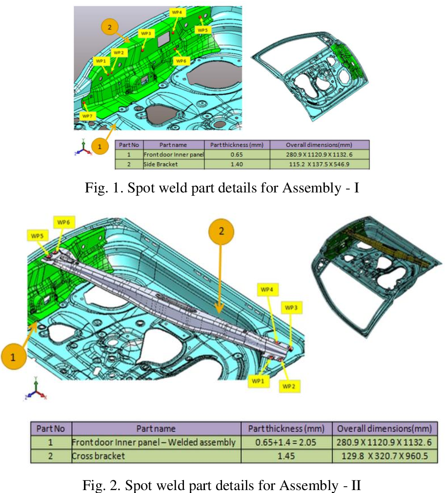
The goal is to verify two things:
- Reachability: Can the robot physically position the gun at the weld location?
- Clearance: Once in position, is there enough space around the gun to operate without colliding with the part, the fixture, or other components?
Let's return to the Johnson Controls specification to see how a major Tier 1 supplier formally manages this risk.
[PDF] Johnson Controls Automotive Experience Global Supplier ...
These sections detail the non-negotiable requirements for proving out weld access.
In the "Tooling Standard General Requirements" section, find Note1 and Note2. These mandate a 3D CAD review for weld gun access and even consider the robot technician's line of sight for programming. Read the section titled "Welding feasibility study". It explicitly states the supplier is responsible for delivering a simulation proving weld access. Finally, review the "Torch position – Torch angle" section. This provides specific geometric constraints, such as the required clearance (5mm) from any fixture point and allowable work/travel angles.
If a weld becomes inaccessible due to an ECO, it is a major issue. It could force a costly redesign of the part, require expensive specialized welding equipment, or even change the joining method entirely (e.g., to MIG welding), which has its own cycle time and quality implications.
✅ Item 3: Fixturing and Locating
The welding fixture is the heart of the BIW assembly cell. It uses a system of pins and clamps to hold all loose sheet metal parts in their precise locations (defined by the GD&T) while the robot welds them.
An ECO that changes the shape of a part will almost certainly require a change to the fixture. The DFA review must assess:
- Locating Scheme: Do the primary 3-2-1 locating points (datums) need to move?
- Clamping: Can the existing clamps still hold the part firmly without distorting it? Are new clamps needed?
- Tooling Modification: What is the cost and lead time to modify the fixture? This can be a significant factor in the ECO's overall business case.
A core principle is that clamps must be supported by "backup" details to prevent the sheet metal from bending under clamping force. The resource LINK details this in the "Clamping concept" section, emphasizing that the goal is to "consistently locate the parts and not bend, deflect, or move the parts once clamped up."
3. Your Task: Perform a DFA Review on the Bracket ECO
Let's apply this checklist to our BIW bracket assembly.
Scenario:
- Original Design: A simple L-bracket (Part A) is spot-welded to a structural rail (Part B). The assembly is simple, and all weld flanges have wide-open access.
- ECO Design: To address a newly identified load case, we have added a triangular gusset (Part C) that ties into both the L-bracket and the rail.
Your Task: As the lead engineer, you are now reviewing this change. Based on the DFA principles we've discussed, identify the potential assembly issues introduced by the addition of Part C.
-
Assembly Sequence:
- Question: The team is debating whether to make the gusset (Part C) a separate piece or to integrate it into the stamping for the L-bracket (Part A). From a DFA perspective (specifically, part count), which is preferable and why? What might be a DFM argument against your choice?
-
Weld Access:
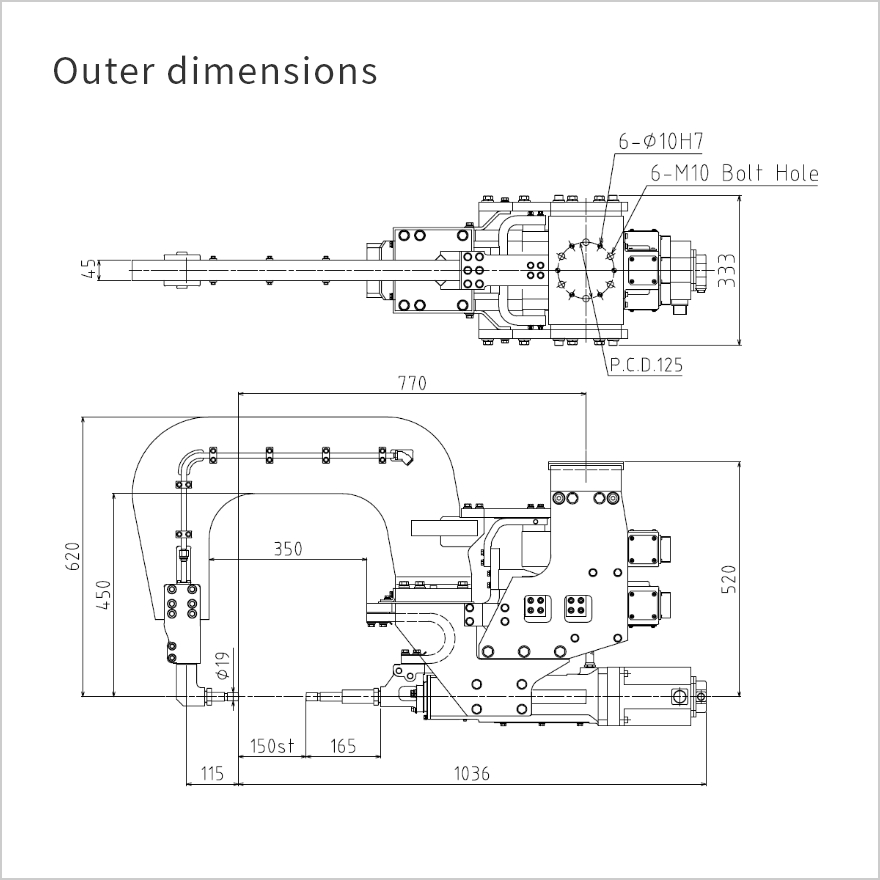
- Question: The new gusset (Part C) is now located 100mm away from a vertical flange on the rail (Part B) where two spot welds are planned. Looking at the drawing of the spot welding gun (LINK), which has an overall height of 402 mm and an arm depth (throat) of approximately 250-300mm, what is the primary access concern you would raise immediately?
-
Fixturing:
- Question: The new gusset adds a third component to the fixture. This requires new locators and clamps. The manufacturing engineer is concerned about clamping the thin edge of the triangular gusset. Referencing the principles in the Johnson Controls "Clamping concept" (LINK, section 2), what specific instruction would you give them to ensure the gusset is held securely without being damaged or distorted?
-
Problem Solving:
- Challenge Question: Your weld feasibility simulation confirms that the standard robotic gun cannot access one of the critical welds on the L-bracket because the new gusset is in the way. The project timing is critical, and a full part redesign is not an option. Propose two distinct solutions you could investigate to solve this joining problem.
Click here for my analysis and suggested answers.
-
Assembly Sequence:
- DFA Preference: Integrating the gusset into the L-bracket is strongly preferred from a DFA standpoint. This follows the core principle of part count reduction. It eliminates the need for an operator/robot to handle and load a third part, reducing cycle time and potential for loading errors.
- DFM Counter-Argument: Integrating the gusset could make the flat pattern of the L-bracket highly irregular, leading to poor material utilization (as we saw in the last lesson). It could also require a more complex and expensive stamping die (e.g., needing a cam slide to form an undercut feature). This is a classic trade-off that engineers must balance.
-
Weld Access:
- The primary concern is a collision risk between the "back" of the C-frame of the weld gun and the new gusset. While the electrodes might reach the weld flange, the large body of the gun must also have clearance. With only 100mm of space, and a gun body that is significantly larger, it's highly likely the gun cannot be positioned correctly without the gusset interfering with its path.
-
Fixturing:
- The key instruction would be to ensure that any clamp applied to the gusset is directly opposed by a "clamp backup detail". This means the fixture must include a solid block of steel directly underneath the point where the clamp contacts the part. This support prevents the thin sheet metal gusset from bending or deflecting under the high force of the pneumatic clamp, ensuring dimensional stability during welding.
-
Problem Solving (Challenge Question):
- Solution 1 (Alternative Joining): Propose changing that specific inaccessible joint from a spot weld to a MIG/MAG weld or a laser weld. These processes use a smaller "torch" or "head" that may be able to access the joint. This would require a different robot and has cycle time/cost implications but may be feasible. Another option could be a mechanical fastener like a Self-Piercing Rivet (SPR).
- Solution 2 (Tooling Change): Investigate using a different type of spot welding gun. For example, an X-gun (also called a pinch gun) has a different geometry from a C-gun and may have better access. Alternatively, a specialized, custom-designed gun could be commissioned, although this is an expensive and time-consuming option typically reserved as a last resort.
Conclusion
You have now performed a high-level DFA review of an ECO, a critical activity for any automotive design engineer. You've seen that a part's impact on assembly is a complex issue involving sequence, ergonomics, tooling access, and fixturing strategy. A seemingly simple design change can have far-reaching consequences on the factory floor.
Key Takeaways:
- DFA focuses on making the assembly of parts faster, cheaper, and more robust.
- For BIW, the most critical DFA checks involve assembly sequence, error-proofing (Poka-Yoke), and ensuring clear access for robotic welding guns.
- Issues found during a DFA review have direct impacts on cost (fixture modification, special equipment) and timing (slower cycle time, tooling lead time).
- Real-world automotive design is governed by detailed supplier and internal standards (like the Johnson Controls document) that formalize these DFA requirements.
The issues we've uncovered today—potential for incorrect loading, inaccessible welds—are all potential failure modes. In our next lesson, we will formalize this risk analysis by updating the Design Failure Mode and Effects Analysis (DFMEA) to reflect the changes introduced by our ECO.
Can't find a good explanation? Sign up and we'll make it for you
Sign up