
Welcome to the third lesson of our sheet metal module. In our last session, we successfully modeled the multi-part BIW assembly, implementing the design changes specified in the Engineering Change Order (ECO). We focused on the practical CAD work and the critical design rules for creating manufacturable weld flanges.
Today, we shift from implementation to analysis. An ECO is never approved without a thorough evaluation of its consequences. One of the most significant impacts is on cost, and in sheet metal stamping, the primary cost driver is the raw material. This lesson will equip you to analyze how a design change affects material consumption.
Our learning outcome is to analyze the ECO's impact on material utilization by comparing original and revised flat patterns. We'll define what material utilization is, why it's a critical metric for a design engineer, and how to calculate it by evaluating different nesting strategies for your flat patterns.
1. The Economics of Material Utilization
In high-volume automotive manufacturing, every gram of steel matters. A seemingly small design change can add or remove tons of steel from the annual forecast for a vehicle program. As a lead engineer, you are directly accountable for the cost implications of your designs.
To understand the financial importance of this topic, please read the first few sections of the following article.
Automotive Stamping Material Utilization: Maximizing Yield & Profits
This article from Shao-Yi provides a clear, industry-focused explanation of why material utilization is paramount in automotive stamping.
Focus on these key areas: The TL;DR and The Economics of Material Utilization: Absorb the core statistic that raw material constitutes 60-70% of a stamped part's total cost. Calculating Material Utilization Rates: Understand the fundamental formula. This is the central equation for our analysis today.
As the article highlights, the industry-standard formula for material utilization is:
Let's break this down:
- Net Weight of Part: The weight of the final, trimmed part that gets assembled into the car. This is calculated from the volume of your 3D model and the material density.
- Gross Weight of Material Consumed: The weight of the rectangular section of the steel coil required to produce one part (or one set of parts per press stroke). This is determined by the coil width and the pitch (the length of coil fed into the die for each stroke).
The difference between these two weights is scrap, also known as offal. Our goal is to minimize this scrap.
2. From 3D Form to 2D Flat Pattern
The first step in analyzing utilization is to generate the 2D flat pattern from the 3D formed part. As we discussed on Day 4, your CAD software does this by "unfolding" the bends based on principles like K-factor or bend allowance, which account for material stretching and compression.
Any modification made to the 3D part—adding a hole, changing a flange length, modifying a corner radius—will alter the shape and area of its flat pattern. This new shape is the input for our utilization analysis.
3. Nesting: The Key to High Utilization
A flat pattern's shape dictates how efficiently it can be arranged on the steel coil. This arrangement is called nesting. Poor nesting leads to excessive scrap and high part cost. An effective nesting strategy is one of the most powerful tools a design engineer has to control cost.
The article you just read discusses several nesting strategies. Let's examine them more closely.
Automotive Stamping Material Utilization: Maximizing Yield & Profits
We will now look at the core strategies for arranging parts on a coil.
Focus on the Nesting Strategy Comparison table. Understand the visual difference and the typical yield percentages for One-Up, Two-Up, and Mirror / Two-Pair layouts.
To summarize the key strategies:
- One-Up: One part is stamped per stroke. Simple, but often inefficient, leaving large amounts of scrap.
- Two-Up / Mirror (Two-Pair): Two parts are stamped per stroke. This is often far more efficient, especially for non-rectangular parts. By mirroring or rotating the second part, it can be "nested" into the negative space of the first, like puzzle pieces. This significantly reduces the required pitch and/or coil width.
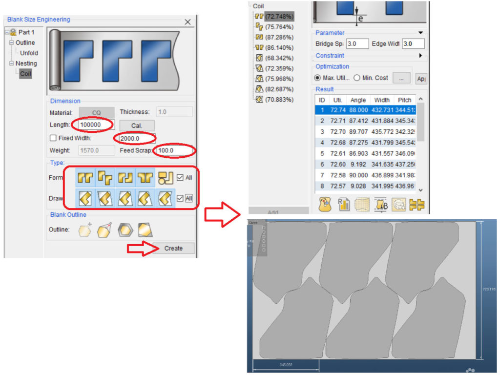
The image below shows a typical software interface used by manufacturing and cost engineering teams to run these nesting simulations and find the optimal layout.
4. Your Task: Analyze the ECO's Impact on the Bracket
Let's apply this to our BIW bracket ECO. Assume the original part was a simple L-bracket. Our ECO added a new reinforcement flange and a lightening hole to the design. This change will alter the flat pattern. Your task is to analyze the material utilization impact.
Scenario Data:
- Material: DP600 Dual-Phase Steel
- Thickness (): 1.8 mm
- Density (): 7.85 g/cm³ (or 7.85 x 10⁻⁶ kg/mm³)
- Standard Coil Widths: Available in 5 mm increments (e.g., 200 mm, 205 mm, 210 mm).
- Scrap Bridge: A minimum of 5 mm is required between adjacent blanks and from the blank to the coil edge.
Part 1: Original Bracket Analysis
The original bracket's flat pattern is a simple rectangle.
- Flat Pattern Dimensions: 200 mm x 150 mm.
-
Calculate Net Area and Weight:
- Net Area =
- Net Weight = Net Area Thickness Density =
-
Determine Nesting Strategy and Gross Area:
- For a simple rectangle, a One-Up layout is most straightforward.
- Required Coil Width = Part Width + (2 Scrap Bridge) = .
- Pitch = Part Length + Scrap Bridge = .
- Gross Area Consumed per Part = Pitch Coil Width = .
-
Calculate Material Utilization:
- Utilization = (Net Area / Gross Area) 100 = () 100 = 91.5%
- This is very high, as expected for a simple rectangular part that nests almost perfectly.
Part 2: Your Turn - Revised Bracket Analysis
The ECO has changed the design. The new flat pattern is an irregular "T" shape.
- Flat Pattern Bounding Box: 240 mm long x 180 mm wide.
- Net Area: Due to the irregular shape and the new lightening hole, the net area of the flat pattern is 31,500 mm².
Your task is to calculate the material utilization for this revised part.
Question 1: A simple One-Up layout for this T-shaped part would be very inefficient. What alternative nesting strategy, discussed in the article, would be much better for an irregular shape like this?
Question 2: Assume you use your proposed strategy. The two nested parts fit optimally within a new bounding box of 250 mm x 250 mm.
- Calculate the Gross Area consumed per part.
- Calculate the new material utilization percentage.
Question 3: Compare the results. By what percentage did the material utilization change as a result of the ECO? Did the change improve or worsen material efficiency?
Take your time to perform the calculations. This is exactly the kind of analysis you would present in a design review to justify or challenge an engineering change.
Click here to see the solution and my analysis.
Answer 1: For an irregular "T" shape, a Mirror / Two-Pair nesting strategy is ideal. By rotating the second part 180 degrees, it can interlock with the first, minimizing the overall bounding box and scrap.
Answer 2:
-
Gross Area (Two Parts):
- The two nested parts fit in a 250 mm x 250 mm box.
- Pitch = 250 mm + 5 mm Scrap Bridge = 255 mm.
- Coil Width = 250 mm + (2 5 mm Scrap Bridge) = 260 mm.
- Gross Area for two parts = Pitch Coil Width = .
-
Gross Area (Per Part):
- Gross Area per part = .
-
New Material Utilization:
- Utilization = (Net Area / Gross Area per part) 100 = () 100 = 95.0%.
Answer 3:
- Original Utilization: 91.5%
- Revised Utilization: 95.0%
- Change: +3.5%
Conclusion: In this scenario, the ECO, despite creating a larger and more complex part, actually improved material utilization. This counter-intuitive result happens because the new irregular shape allowed for a highly efficient interlocking nest, reducing the percentage of scrap relative to the part's area. This is a critical insight: part size alone does not determine material efficiency; the shape of the flat pattern and the resulting nesting strategy are what truly drive utilization.
5. Advanced Analysis: Beyond Flat Patterns
For simple brackets, an area-based calculation is a good estimate. However, for complex deep-drawn parts like body sides or fenders, two other factors come into play.
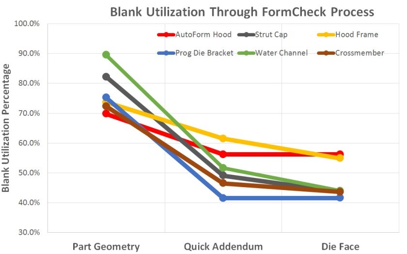
- Addendum & Binder: The flat pattern from your CAD model only represents the final part. The actual blank stamped in the press is much larger because it includes extra material called the addendum or binder wrap. This material is used to grip the blank in the die and control metal flow during the drawing operation to prevent defects. This addendum is trimmed off and becomes scrap. As the graph below shows, blank utilization decreases as these manufacturing elements are added to the initial part geometry.
- Thickness Variation: The assumption that thickness is uniform is not entirely accurate. During stamping, material stretches and thins in some areas while compressing and thickening in others. For a highly accurate weight and cost calculation, engineers use Finite Element Analysis (FEA) to simulate the stamping process and calculate the final part weight based on the varying thickness distribution.
The patent document below describes such a method, providing a glimpse into high-precision cost engineering.
Method for determining material utilization rate of parts for stamping ...
This patent describes a high-precision method for calculating material utilization using FEA. You don't need to understand the complex formulas, but rather the core concept.
Read Step 1 through Step 7 in the "Contents of the invention" section. Focus on the process it describes: using simulation to get the thickness distribution across the part and then using that data to calculate a more accurate weight, which leads to a more precise utilization figure.
This FEA-based approach represents the highest level of accuracy and is used for large, expensive panels where even a fractional percentage improvement in utilization translates to millions of dollars in savings over a vehicle's life.
Conclusion
Today we've moved beyond the geometry of a design change and into its financial and manufacturing consequences. Quantifying the impact of an ECO on material utilization is a core competency for a senior automotive engineer.
Key Takeaways:
- Material utilization is a critical KPI, as raw material accounts for up to 70% of a stamped part's cost.
- The impact of an ECO on utilization is determined by how the change affects the flat pattern's shape and, most importantly, its nesting efficiency.
- Comparing nesting strategies (e.g., One-Up vs. Two-Pair) is essential to optimizing material use and minimizing cost.
- While simple area calculations are useful for initial estimates, advanced analysis for complex parts must account for binder material (addendum) and thickness variations calculated via FEA.
In our next lesson, we will continue our analysis of the ECO's impact, shifting our focus from part cost to assembly cost. We will perform a Design for Assembly (DFA) review to assess how the new design affects the manufacturing process on the assembly line.
Can't find a good explanation? Sign up and we'll make it for you
Sign up