
Good to see you again. The previous lesson established the controlled project record: requirements, interfaces, CAD, validation evidence, supplier inputs, nonconformances, and changes must all be identifiable and linked. Before any component CAD can be credible, though, the team needs a controlled answer to a more basic question: what vehicle environment are we designing into?
In this course, “Rivian-built Amazon EDV” is a simulated engineering context, not a claim that you possess Rivian, Amazon, or supplier proprietary data. Your packaging model must make that boundary visible. It will preserve published vehicle information, isolate the deductions you make from it, label engineering assumptions, and identify who controls every important interface.
By the end of this lesson, you will have a lightweight vehicle-context package that can support the ECU housing, door trim, and HVAC outlet projects without turning unknown vehicle details into invented facts.
A packaging model is a controlled decision model
A van outline with a few dimensions is useful, but it is not yet a packaging model. A usable packaging model combines five things:
- A declared vehicle configuration — for example, a Delivery 500 reference context, with a source and retrieval date.
- A common coordinate system and datums — so every component team places geometry consistently.
- Reference envelopes and zones — exterior bounds, design spaces, keep-outs, and service envelopes.
- Interfaces — defined connections between component, vehicle structure, electrical, HVAC, styling, and manufacturing teams.
- Evidence status — whether each item is public fact, a derived value, a working assumption, or still unknown.
The most important discipline is this:
A dimension being publicly available does not make every design conclusion drawn from it valid.
For example, a published overall width with mirrors is useful for a vehicle envelope. It is not a valid body-side datum for a door-trim carrier, and it says nothing about the inner-door structure, clip holes, window mechanism, or side-impact reinforcement.
Study Rivian’s public fleet-page dimensions as the initial evidence boundary for the vehicle reference model.
Rivian Fleet: Electric Work & Commercial Vans
Read Rivian’s official fleet page to see the distinction between a small set of published vehicle-level dimensions and the much richer information a component packaging model would require.
In the “Dimensions” section, read the Delivery 500 dimension set from the listed overall dimensions. Record the source title, URL, date accessed, vehicle variant, units, and the exact published labels such as “Width (with mirrors).” Do not infer body width, door geometry, axle locations, or component mounting points from this page.
The Delivery 500 public values can support a first-order exterior reference envelope:
| Published item | Appropriate initial use | Not appropriate to infer |
|---|---|---|
| Overall length | Longitudinal exterior envelope | Exact bumper construction, front electronic-module location |
| Overall height | Vehicle-height reference and garage/service envelope | Roof cross-section or internal cargo-headroom allocation |
| Width with mirrors | Maximum external clearance envelope | Body width, door aperture width, or trim width |
| Wheelbase | Vehicle-level reference data | Exact front- or rear-axle coordinates relative to body surfaces |
| Cargo volume | Fleet-use context | Cargo-bay floor plan or bulkhead location |
The Delivery 700 dimensions graphic is useful as a visual reminder that vehicle-level dimensions describe the outer vehicle rather than its internal package.
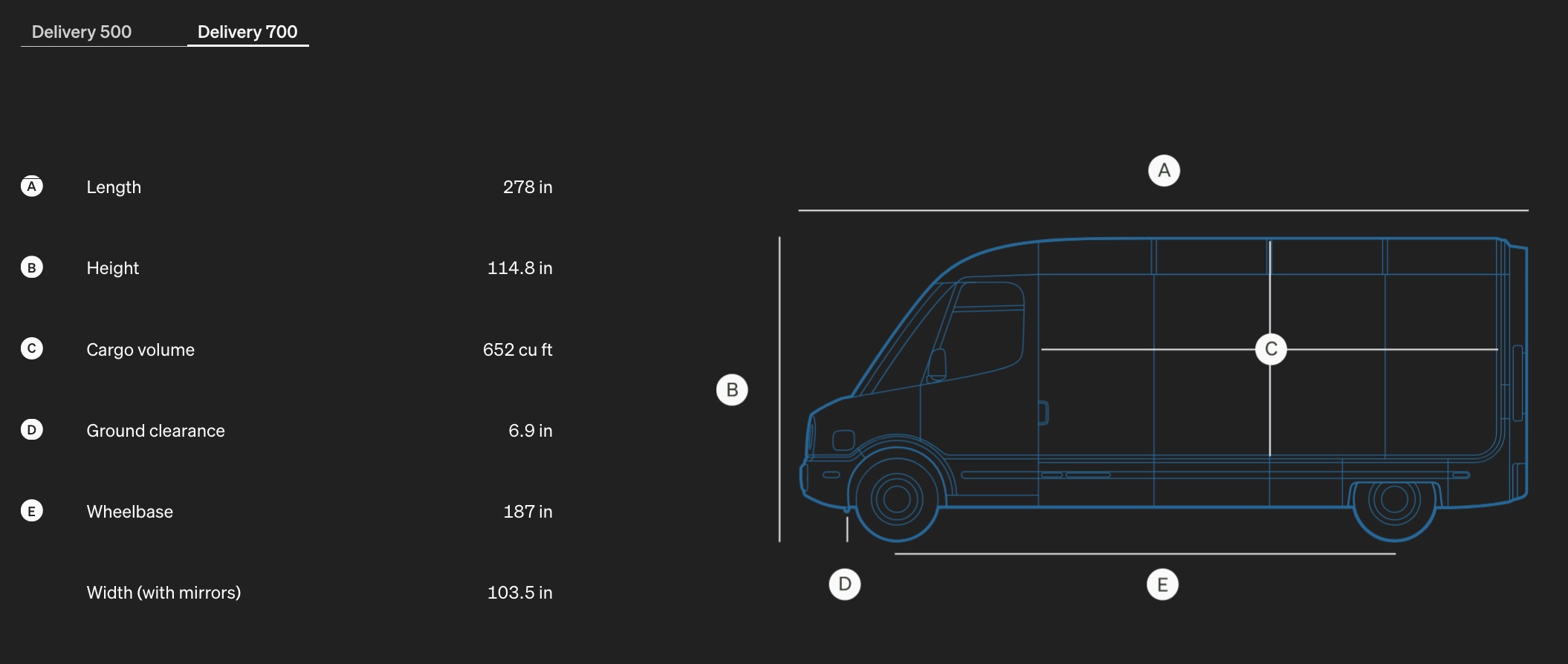
For this course, choose one declared reference configuration for each baseline. A sensible starting choice is:
CFG-VEH-001 Rev A — Simulated Rivian-built Amazon EDV, Delivery 500 public-envelope reference
That name is intentionally cautious. It says that the model uses a Delivery 500 public-envelope reference; it does not claim that the model reproduces the vehicle’s actual engineering package.
Separate facts, derived values, assumptions, and decisions
A common early-project mistake is to place all dimensions in one sketch and treat them as equally trustworthy. Instead, every context-model item needs a type and a confidence level.
Use four evidence types:
| Type | Meaning | Example |
|---|---|---|
| Public fact | Directly supported by an identified public source | Published Delivery 500 overall length |
| Derived value | Calculated or geometrically constructed from cited data, using a recorded method | Metric conversion of a published inch dimension |
| Engineering assumption | A provisional input adopted so engineering can proceed | ECU service-access clearance |
| Design decision | A team choice made among feasible options | Locating the assumed ECU on a serviceable mounting rail |
An assumption is not a mistake or a weakness. It is a temporary stand-in for missing knowledge, provided that it is visible, owned, risk-assessed, and actively reviewed.
What is an Assumptions Log? Project Management in Under 5
Watch “What is an Assumptions Log?” from Online PM Courses – Mike Clayton for a concise explanation of why assumptions must be recorded rather than left inside individual engineers’ CAD models or notes.
Watch the definition to distinguish an assumption from a confirmed fact and to connect assumptions with project risk. Then watch the log fields, focusing on ID, category, confidence, impact, owner, validation plan, review date, and status. Use only the fields that will genuinely be maintained.
Use confidence and impact separately
“High confidence” does not mean “low consequence.” A published external-envelope length can be high confidence but relatively low importance to an ECU mounting design. Conversely, an assumed electrical-isolation keep-out may have low confidence but very high impact.
Use this simple scale:
| Confidence | Meaning | Typical evidence |
|---|---|---|
| High | Direct source is controlled, clear, and applicable to the selected context | Official published specification with an exact configuration match |
| Medium | Supported, but incomplete, indirect, or dependent on interpretation | Public image, credible secondary source, or a limited teardown observation |
| Low | Engineering placeholder with no confirming vehicle evidence | Assumed hardpoint layout or service-removal direction |
| Unknown | No reliable input exists yet | Door-inner panel shape, HVAC duct interface, ECU mounting rail |
Add an impact if wrong rating independently: low, medium, high, or critical. This tells the team which assumptions must be closed before a design gate.
Build the assumptions and evidence log
Create EDV-SIM-VEH-ASM-001 Rev A in the controlled project record established previously. Use one row per meaningful input.
| ID | Type | Statement | Confidence | Impact if wrong | Owner role | Closure method | Status |
|---|---|---|---|---|---|---|---|
PUB-VEH-001 | Public fact | Delivery 500 overall length is listed as 248.5 in on Rivian’s fleet page | High | Low | Vehicle Packaging Lead | Preserve source capture and review applicability | Confirmed public datum |
DRV-VEH-002 | Derived value | CAD dimensions use millimetres converted from the cited inch values | High | Low | CAD Integration Lead | Check conversion and units at baseline review | Confirmed |
ASM-ECU-001 | Engineering assumption | A forward serviceable electronics-zone envelope is reserved for ECU study | Low | High | Electrical Integration Lead | Obtain controlled package input or approve a formal package allocation | Open |
ASM-DOOR-003 | Engineering assumption | Driver door trim interfaces are represented by a supplied simplified inner-door reference surface | Low | High | Closure Systems Lead | Replace with approved body-side interface data | Open |
ASM-HVAC-002 | Engineering assumption | HVAC outlet duct inlet is represented by a nominal round duct connection in the instrument-panel zone | Low | High | HVAC Integration Lead | Replace with released duct interface geometry | Open |
A confirmed assumption should not simply be overwritten. Preserve the original row and change its status to verified, disproved, or superseded by controlled source. This retains the reasoning history needed when a later change affects the design.
Establish a common vehicle reference frame
Your component models need a shared spatial language. Without one, an ECU model can be “correct” in its own document but unusable in an assembly because its axes, origin, or left-right convention differ from the vehicle master.
For this simulated program, define the vehicle coordinate system explicitly:
| Reference | Definition for the simulated model | Evidence status |
|---|---|---|
VEH-PLN-00 | Nominal ground plane | Assumption, unless a controlled chassis datum is supplied |
VEH-PLN-01 | Vehicle longitudinal center plane | Assumption based on symmetry convention |
VEH-PLN-02 | Nominal front-most exterior plane | Derived from the public overall-length envelope |
| X axis | Positive toward the rear of the vehicle | Program convention |
| Y axis | Positive toward the vehicle left side | Program convention |
| Z axis | Positive upward from the nominal ground plane | Program convention |
These are integration datums, not manufacturing datums for the actual van. They exist so that all course work uses one coordinate convention.
Model only what you can justify
In an Onshape document called EDV-SIM-VEH-PKG, create a Part Studio named 00_Vehicle_Reference. Build the public vehicle envelope as transparent reference geometry or a clearly named reference solid. Keep it visually and structurally separate from component geometry.
Use these naming conventions:
| Model item | Example name | Meaning |
|---|---|---|
| Public outer envelope | PUB_ENV_D500_EXT | Overall reference volume based on public dimensions |
| Mirror-inclusive clearance envelope | PUB_ENV_D500_MIRROR | Maximum width boundary; not a body-surface reference |
| Assumed ECU zone | ASM_ZONE_ECU_FWD_01 | Provisional design space only |
| Assumed door package | ASM_IF_DOOR_INNER_01 | Simplified input awaiting vehicle-interface data |
| Assumed HVAC duct interface | ASM_IF_HVAC_DUCT_01 | Placeholder duct connection and package zone |
| Service-removal volume | ASM_SVC_ECU_REMOVE_01 | Assumed swept volume needed to remove an ECU assembly |
Do not draw precise structural rails, door apertures, windshield profiles, dashboard cross-car beams, wiring harnesses, or HVAC ducts merely because a vehicle outline suggests where they might be. A sketch that looks realistic can be more dangerous than a plainly labeled placeholder because it invites false confidence.
A useful packaging model is therefore deliberately uneven: exterior geometry may be relatively well supported, while internal interfaces remain coarse and explicitly provisional.
Represent package zones and keep-outs as engineering constraints
A package zone is space provisionally allocated to a component or function. A keep-out is space the component must not occupy. A service envelope is the space required to install, remove, inspect, or operate something.
For the three course projects, define zones at the level appropriate to the evidence you have:
| Project | Initial reference geometry | High-value package constraints to show |
|---|---|---|
| High-voltage ECU housing | Assumed electronics-zone volume and mounting-interface planes | Harness approach, connector access, removal direction, electrical separation reserve, thermal and splash-risk placeholders |
| Driver-door trim carrier | Assumed inner-door surface and perimeter | Window-regulator reserve, speaker zone, switch/handle openings, clip-access direction, adjacent-trim clearance |
| Driver-zone HVAC outlet | Assumed bezel, duct inlet, and surrounding instrument-panel envelope | Vane sweep, duct connection, display/driver-reach reserve, assembly direction, anti-rattle interfaces |
Classify each spatial constraint:
| Constraint class | Meaning | Change authority |
|---|---|---|
| Hard keep-out | No intrusion is allowed without an approved interface change | Interface owner |
| Soft reserve | Intrusion may be negotiated, but requires review | Interface owner and affected component owners |
| Service envelope | Space required during assembly, removal, tooling, or inspection | Component owner, verified by integration |
| Manufacturing reserve | Space needed for draft, mold action, tool access, or assembly fixture clearance | Manufacturing or supplier interface owner |
For example, an ECU connector’s assumed harness-bend space should not be modeled as a decorative box. It should carry an identifier, owner, state, and basis. If the harness package later changes, the team can find every feature and verification activity dependent on that zone.
Assign ownership to interfaces, not just components
Components often have obvious owners. Interfaces are harder because they sit between organizations. A door-trim carrier may be owned by Interior Trim, while the attachment holes are owned by Closure Systems; the HVAC outlet may be owned by Interior Trim, while airflow and duct geometry are owned by HVAC Integration.
The NASA Interface Management Process graphic captures the underlying discipline: interface requirements are managed throughout design and integration, then captured in controlled interface work products.
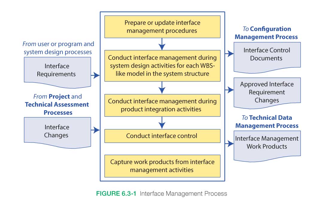
For every interface, assign:
- Interface owner — accountable for maintaining the Interface Control Document, coordinating changes, and resolving conflicts.
- Side A owner — accountable for the first mating system.
- Side B owner — accountable for the second mating system.
- Approving roles — roles required to accept a changed interface.
- Verification owner — role that confirms the assembled interface meets its requirement.
Use role names, not individual names. A person may execute the work, but the engineering responsibility remains stable when personnel change.
Create an Interface Control Matrix
Create EDV-SIM-VEH-ICM-001 Rev A. Start with the interfaces below.
| Interface ID | Interface | Interface owner | Side A owner | Side B owner | Controlled content |
|---|---|---|---|---|---|
IF-ECU-001 | ECU housing to vehicle mount structure | Vehicle Packaging Lead | ECU Design Lead | Body/Chassis Integration Lead | Mounting planes, fastener locations, load paths, installation direction |
IF-ECU-002 | ECU housing to harness/connectors | Electrical Integration Lead | ECU Design Lead | Electrical Architecture Lead | Connector approach, clearance reserve, retention, service access |
IF-DOOR-001 | Door trim carrier to inner door | Closure Systems Lead | Interior Trim Lead | Closure Systems Lead | Locators, clips, screws, build variation, removal direction |
IF-DOOR-002 | Door trim to handle and switch modules | Interior Trim Lead | Door Trim Lead | HMI/Interior Electronics Lead | Openings, attachment zones, service sequence |
IF-HVAC-001 | HVAC outlet to duct | HVAC Integration Lead | HVAC Outlet Lead | HVAC Duct Lead | Duct outlet geometry, sealing/retention, airflow direction |
IF-HVAC-002 | HVAC bezel to instrument panel | Interior Integration Lead | HVAC Outlet Lead | Instrument Panel Lead | Visible gap, flushness, datum scheme, surface boundary |
Each controlled interface entry should contain more than names. Its minimum fields are:
| Field | Why it matters |
|---|---|
| Interface ID and title | Gives the interface a stable traceability key |
| Current configuration and revision | Prevents use of obsolete interface geometry |
| Coordinate system | Ensures both sides use the same spatial reference |
| Geometry reference | Links to the Onshape Part Studio, sketch, assembly, or neutral-file source |
| Functional requirement | States what the interface must accomplish |
| Nominal dimensions and allowable variation | Defines the engineering agreement |
| Keep-outs and service envelopes | Captures non-contact spatial needs |
| Owner and approvers | Defines decision authority |
| Verification method | States how fit, clearance, access, or function will be shown |
| Assumptions and open issues | Makes uncertainty visible |
| Change reference | Connects interface revision to an ECR or ECO when altered |
Build the controlled context model in Onshape
The objective is not to create a visually complete digital mock-up. The objective is to create a model that is traceable, reusable, and resistant to accidental misuse.
Recommended document structure
| Onshape item | Purpose |
|---|---|
EDV-SIM-VEH-PKG document | Authoritative home for the common vehicle context |
00_Vehicle_Reference Part Studio | Public outer envelope, planes, axes, coordinate convention |
01_Assumption_Zones Part Studio | Clearly labeled ECU, door, HVAC, service, and keep-out volumes |
02_Interface_Skeleton Part Studio | Interface planes, points, simplified surfaces, named reference geometry |
EDV-SIM-VEH-ASM assembly | Lightweight integration view of vehicle reference and three component envelopes |
Version V0.1_Public_Baseline | Captures the initial public-data model |
Version V0.2_G1_Package_Baseline | Captures approved assumptions and initial component interfaces |
In CATIA terms, the vehicle reference and interface skeleton perform a role similar to a controlled product context with published reference elements. In a CATIA/ENOVIA environment, the vehicle package, component parts, interface documents, and revisions would normally be managed as linked configuration-controlled objects. In Onshape, use named versions for frozen CAD states and maintain the formal approval, assumption, and baseline status in your controlled project workbook.
A practical build sequence
-
Create the evidence register first. Enter the public dimensional facts, source reference, confidence, and applicability notes before modeling anything.
-
Set the document units and coordinate convention. Use millimetres if that will be your design standard, but preserve the original published units and record the conversion method in the evidence register.
-
Create the exterior reference envelope. Model only the gross bounding volume justified by the public dimensions. Mark mirror-inclusive width as a clearance condition, not a nominal body width.
-
Create named planes and axes. Add the vehicle center plane, nominal ground plane, front exterior plane, and the three axes defined earlier.
-
Add assumption-based component zones. Build simple, distinguishable volumes for the ECU, driver door, and driver-zone HVAC projects. Every volume must reference an
ASMlog entry. -
Add hard keep-outs and service envelopes. Give each one an ID and an owner. Avoid unnamed construction geometry.
-
Publish a lightweight assembly view. Insert the reference geometry and component envelopes into
EDV-SIM-VEH-ASMso that upcoming component designs can be checked in a shared vehicle context. -
Freeze the baseline. Create the named Onshape version, export a view or screenshot where needed, update the Master Record Index, and create
BASE-VEH-G1-01.
A design team may modify a working zone in its own workspace, but it should not silently modify the shared vehicle reference. Any change to a shared interface must be proposed, impact-assessed, approved by the interface owner, and then incorporated into a new controlled baseline.
The G1 vehicle-context baseline
Before detailed ECU, door, or HVAC CAD starts, review the context package at a preliminary gate. The purpose is not to prove that every vehicle feature is known. It is to prove that uncertainty is contained and visible.
Your BASE-VEH-G1-01 should contain:
CFG-VEH-001 Rev A, identifying the simulated vehicle reference configuration.- A captured source record for the public dimensions used.
EDV-SIM-VEH-ASM-001 Rev A, the assumptions and evidence log.EDV-SIM-VEH-ICM-001 Rev A, the Interface Control Matrix.- The Onshape version
V0.2_G1_Package_Baseline. - A package screenshot or PDF with the coordinate frame, reference envelope, zones, and keep-outs visible.
- An open-risk list for every high-impact, low-confidence assumption.
- A decision log stating that the model is authorized for concept development only, not tooling, production release, or supplier manufacture.
The baseline decision should include an explicit restriction such as:
This package model is approved for simulated concept design. Internal component locations, mounting interfaces, door-inner geometry, HVAC duct geometry, and service clearances remain engineering assumptions unless identified otherwise in the controlled evidence register.
That sentence prevents a downstream user from mistaking an early packaging model for released vehicle data.
Key takeaways
A controlled EDV context model is not a claim to proprietary vehicle knowledge. It is a transparent engineering environment that lets work proceed while showing exactly what is known and what is provisional.
The core practices are:
- Use public vehicle data only for the purposes it can genuinely support.
- Distinguish public facts, derived values, engineering assumptions, and design decisions.
- Record confidence, impact if wrong, ownership, and a closure plan for every meaningful assumption.
- Establish a common vehicle coordinate system before sharing component geometry.
- Model reference envelopes, zones, keep-outs, and service volumes with clear identifiers and evidence status.
- Give each interface an owner, two technical sides, a controlled definition, and a verification method.
- Freeze the vehicle context as a baseline before component CAD begins.
Next, you will formalize the PLM lifecycle around this model: part numbers, metadata, revisions, maturity states, EBOM and MBOM views, approvals, and release actions in Onshape, mapped to CATIA and ENOVIA concepts.
Can't find a good explanation? Sign up and we'll make it for you
Sign up