
Welcome back. In the last lesson, you created a controlled simulated EDV vehicle context: shared coordinates, assumption-based package zones, interface ownership, and a G1 package baseline. That context is only useful if the CAD, requirements, BOMs, drawings, assumptions, and approvals remain connected as the design evolves.
This lesson establishes a practical product-lifecycle-management approach for the course. You will use native Onshape controls where your subscription makes them available, and a small set of controlled templates where they do not. The objective is not to imitate every capability of a production ENOVIA deployment. It is to maintain a defensible chain from a working model to an approved, reproducible engineering baseline.
By the end, you should be able to distinguish a workspace, version, revision, baseline, and release; assign stable part numbers and useful metadata; maintain an engineering BOM and a manufacturing BOM view; and explain how this workflow corresponds to CATIA and ENOVIA practice.
PLM controls a product definition, not merely CAD files
A mechanical part is rarely released alone. A production-intent ECU base, for example, is defined by more than its solid model:
- the part and assembly CAD;
- its material and finish definition;
- drawing and GD&T;
- requirements and verification status;
- approved interfaces and packaging references;
- EBOM entries and manufacturing allocation;
- DFMEA and special characteristics;
- approval decisions and change history.
PLM is the discipline of keeping those items identifiable, related, and valid for a particular configuration. The practical question it answers is:
What exact product definition was approved, for what purpose, by whom, and what evidence supports it?
This distinction matters when an engineer asks for “the latest CAD.” A later workspace may contain promising development work, but the released revision remains the authorized product definition until a new revision completes review and approval.
Five terms that must not be confused
| Term | Practical meaning | Example in this course |
|---|---|---|
| Workspace | A mutable place where active design work occurs | You alter ECU rib thickness and add a gasket compression stop. |
| Version | An immutable point-in-time snapshot of an Onshape document | V0.2_G1_Package_Baseline freezes the vehicle-context model. |
| Revision | The formally identified approved issue of an object | ECU base part EDV-000123 Rev A, then Rev B after an approved change. |
| Baseline | A controlled, coherent set of linked items valid for a defined purpose | BASE-VEH-G1-01 includes vehicle package CAD, assumptions, interfaces, and open risks. |
| Release | The approval action that authorizes a defined revision or baseline for stated use | “Released for simulated design review” is not the same as “released for production tooling.” |
A version is not automatically a revision, and a revision is not automatically a baseline. A version freezes a document state. A revision identifies an approved object issue. A baseline collects the mutually compatible revisions, versions, and supporting records needed to reproduce a decision.
Study Onshape’s terminology and release behavior now. It gives the native meanings of the states you will use throughout the projects.
Read “Release Management” from Onshape Help to establish the distinction between editable workspaces, immutable versions, release candidates, and released revisions.
In the “Terminology” section, read from the definition of Version through the release-state definitions, focusing on the core terms. Then read the “Workspaces, Versions and Releases” section, beginning with the workflow explanation. Notice especially that design can continue in workspaces while a release candidate is pending.
Onshape’s default managed workflow makes the state model visible:
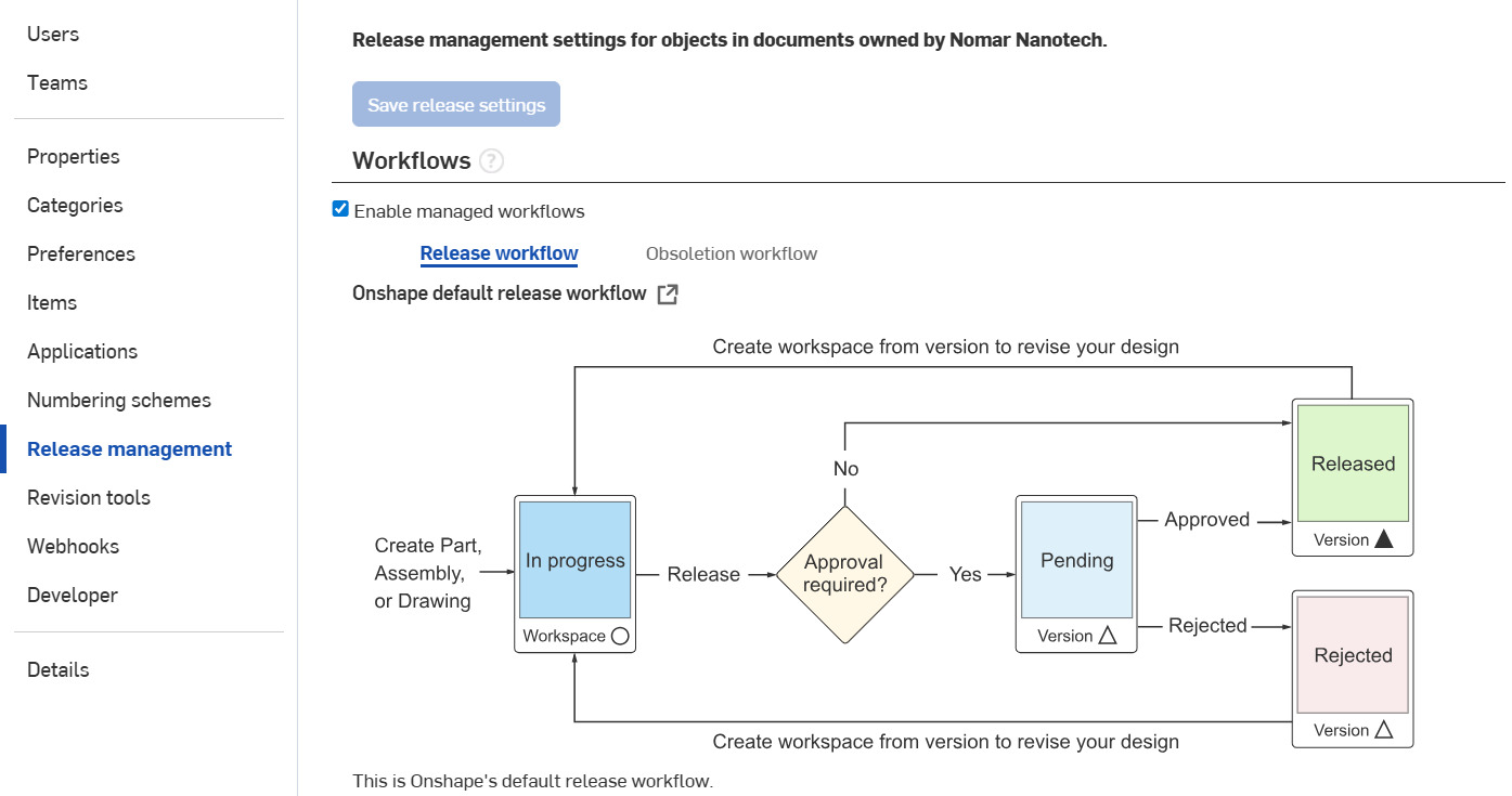
The image makes one crucial principle clear: a released item is not edited in place. To revise it, create a controlled working context from the released version, make the proposed change there, then release a new revision after appropriate review.
A realistic lifecycle for the simulated EDV program
For this course, use four maturity labels in your project-control record:
| Project maturity | Meaning | Native Onshape state where managed workflows are enabled |
|---|---|---|
| In Work | Editable development content; not approved for downstream reliance | In progress |
| In Review | A defined candidate is being checked against requirements and release criteria | Pending |
| Released | Approved for the declared purpose; the revision is the current authorized definition | Released |
| Superseded / Obsolete | No longer current for new use; retained for traceability | Obsolete, where available, or controlled as superseded in the register |
“Frozen” is also common in automotive PLM. Treat it as a gate-control condition, not necessarily a separate native Onshape state: the design may be frozen for a review or validation build while the approval decision is still pending. Record that condition in the baseline manifest and decision log.
The minimum lifecycle sequence
For a component, such as a door-trim carrier or ECU housing, operate the lifecycle as follows:
-
Develop in an In Work workspace.
CAD, drawings, requirements evidence, and BOM data can change. Each important decision should cite its requirement, assumption, interface, or risk record. -
Create a named review version.
Make an immutable Onshape version before a design review, such asV0.4_PDR_Candidate. This is the exact CAD state discussed during the review. -
Assemble the release package.
Confirm that the part, assembly, drawing, EBOM, applicable requirements, open risks, and validation status are coherent. The release package must state its intended maturity: concept, prototype, design validation, tooling, or production. -
Submit the candidate for approval.
If native Onshape Release Management is enabled, create a release candidate containing the relevant revision-managed objects and assign approvers and observers. If it is not enabled, record the same candidate in the controlled release checklist and approval log. -
Release the approved set and create a baseline manifest.
Record the approved revision, the authoritative Onshape version, and links to the associated evidence. Do not merely rename a workspace “Released.” -
Control future changes.
An issue, supplier finding, test failure, or interface update creates a change request. Its impact analysis identifies affected parts, drawings, BOM lines, requirements, risks, tooling, and validation. The resulting revision is released as a new controlled definition.
This preserves two valid truths at once: active development can proceed rapidly, while downstream users retain a stable product definition.
Native controls and controlled-template controls
Your access to the free online version of Onshape may not include managed release workflows or company-level metadata configuration. Do not simulate unavailable system states by typing “Released” into a filename. Instead, make the division explicit.
| Need | Use in Onshape where available | Controlled-template fallback |
|---|---|---|
| Active CAD development | Workspace and document history | Working-status field in the Master Item Register |
| Immutable CAD checkpoint | Named Version | Record document URL/reference, version name, date, and owner |
| Approval workflow | Release candidate, approvers, observers, native Released state | Release checklist, role-based approval log, and decision-log reference |
| Revision status | Native revision-managed object and release history | Revision field controlled only through the approval process |
| Baseline | Released version or named version references | Baseline Manifest listing all included objects and revisions |
| Requirements and evidence links | Document links, properties, files where configured | Requirements Traceability Matrix and Evidence Index |
| EBOM | Onshape assembly BOM | Exported EBOM attached to the baseline manifest |
| MBOM | Available manufacturing structure integration, if provided by enterprise tools | Controlled MBOM and EBOM-to-MBOM reconciliation template |
A controlled template is not a substitute for enterprise PLM. It is a disciplined interim control. Its effectiveness depends on a stable identifier, revision history, named owner, access control, approval record, and a direct link to the relevant Onshape version.
For this course, maintain these five templates:
- Master Item Register — the authoritative list of controlled parts, assemblies, drawings, documents, and their maturity.
- Baseline Manifest — the exact configuration used for a design gate or release.
- Release Checklist and Approval Log — release purpose, readiness checks, approvers, decision, and conditions.
- EBOM–MBOM Reconciliation — every engineering item’s manufacturing disposition.
- Engineering Change Register — issue, impact analysis, approvals, affected objects, and new released revision.
Part numbers and metadata: make objects findable and unambiguous
A part number identifies an item; it should not try to encode the entire history of that item. Avoid embedding material, supplier, revision, or drawing status in the number. Those attributes change and belong in metadata.
Use a simple non-intelligent part-number sequence for the simulated program:
| Object type | Example identifier | Rule |
|---|---|---|
| Part | EDV-000123 | Unique and permanent across the program |
| Assembly | EDV-000450 | Unique and permanent; assembly has its own number |
| Drawing | EDV-DRW-000123 | Controlled document number; references part number and revision |
| Requirement set | EDV-REQ-ECU-001 | Identifies the controlled requirement document |
| Interface definition | IF-ECU-002 | Uses the interface ID created in the Interface Control Matrix |
| Engineering change | ECO-ECU-003 | Identifies one approved change package |
A revision is appended separately:
EDV-000123 Rev A— first released issueEDV-000123 Rev B— next approved issueEDV-000123 Rev Aremains retained and traceable, but is no longer current after Rev B is released.
Do not use EDV-000123-REV-B as a new part number. That creates a false impression that Rev B is a different item rather than a changed definition of the same item.
Minimum metadata for every controlled object
In Onshape, properties drive identification and can populate BOM columns. In your template-based method, the same fields appear in the Master Item Register.
| Field | Example | Why it is needed |
|---|---|---|
| Part number | EDV-000123 | Stable unique identifier |
| Noun name | ECU housing base | Prevents vague labels such as “final base” |
| Description | Molded lower enclosure supporting PCB and gasket interface | Communicates function and scope |
| Revision | Rev A | Identifies the approved issue |
| Maturity | In Work, In Review, Released | States authorization status |
| Owner role | ECU Design Lead | Makes technical accountability clear |
| Make/buy classification | Make — injection molded | Supports manufacturing planning |
| Material/specification | PA66-GF30, supplier grade TBD | Links design intent to material evidence |
| CAD authority | Onshape document and version | Identifies the exact geometric definition |
| Requirement links | REQ-ECU-014, REQ-ECU-031 | Maintains traceability |
| Change reference | ECO-ECU-003 | Explains why the revision changed |
| Effectivity / applicability | Simulated EDV configuration CFG-VEH-001 Rev A | Prevents use in the wrong product context |
Keep descriptive names readable, but do not rely on names for control. ECU_Base_v17_final_final is not traceability. The number, revision, release state, and version reference provide traceability.
EBOM and MBOM represent different questions
An engineering bill of materials (EBOM) describes the product as engineering defines it: the components and quantities needed to meet the design intent. An manufacturing bill of materials (MBOM) describes the product as manufacturing plans, procures, builds, and controls it.
The distinction is especially important for injection-molded automotive assemblies. An ECU engineering assembly may contain a base, cover, gasket, threaded inserts, fasteners, vent, connector seals, and PCB supports. Its manufacturing view may group supplied kits, allocate inserts to an overmolding or insertion operation, separate packaging material, or reflect plant-specific assembly steps.
Onshape automatically generates a BOM from an assembly. This is an excellent starting point for an EBOM, but it is not automatically an approved MBOM.
Read “Bill of Materials” from Onshape Help to see how assembly structure and properties create an interactive BOM, and how its Structured and Flattened views differ.
In the opening section, read the BOM overview. In the video-transcript section, find the paragraph beginning “The table has two view options” and read the view and export guidance. Then read the property synchronization explanation. Focus on which fields can become your controlled metadata columns.
Structured versus flattened BOM
A Structured BOM preserves the hierarchy of the engineering assembly. It is useful in design reviews because it shows which parts belong to which subassembly.
A Flattened BOM lists all instances at one level. It is useful for quantity checks, purchasing summaries, or checking whether a common fastener appears throughout the assembly.
Neither view alone answers the manufacturing question. The manufacturing team may need different grouping, different quantities per operation, non-geometric consumables, supplier kits, or process-specific allocation.
Example: reconcile the ECU EBOM and MBOM
| EBOM item | Engineering role | MBOM disposition | Manufacturing concern |
|---|---|---|---|
ECU base, EDV-000123 | Molded lower enclosure | Molded-component manufacturing item | Resin grade, insert strategy, molding tool status |
ECU cover, EDV-000124 | Molded upper enclosure | Molded-component manufacturing item | Appearance, warpage, sealing-land control |
Gasket, EDV-000125 | Environmental seal | Purchased component allocated to final assembly | Supplier specification, storage, compression control |
Threaded insert, EDV-000126 | Fastener interface | Purchased component allocated to insertion or assembly operation | Insertion method and pullout verification |
M4 fastener, EDV-000127 | Joins cover to base | Purchased component allocated to final assembly | Torque, coating, traceability |
| Threadlocker | Not modeled as CAD geometry | Non-geometric manufacturing item | Process application and cure control |
The reconciliation template must answer, for each EBOM line: Where is this item made, bought, consumed, or intentionally excluded? If an EBOM item has no MBOM disposition, it is an open configuration error, not a harmless administrative omission.
To see the conceptual distinction in a 3DEXPERIENCE environment, watch the selected parts of Dassault Systèmes’ configuration demonstration.
3DEXPERIENCE Configuration of requirements, eBOM and mBOM
Watch “3DEXPERIENCE Configuration of requirements, eBOM and mBOM” by Dassault Systèmes. It shows that requirements, engineering structure, and manufacturing structure are related but distinct configuration views.
Watch the opening for the scope of configuration management. Then watch the engineering BOM view, focusing on the connection between configuration and the engineering product structure. Continue with the manufacturing BOM view and the summary. The product-option examples are more advanced than this course stage; focus instead on the principle that both BOM views must remain linked to the same controlled configuration.
Mapping your practical workflow to CATIA and ENOVIA
CATIA and ENOVIA terminology varies across CATIA V5 with ENOVIA integrations and the 3DEXPERIENCE platform, so treat this as a functional mapping, not a claim of one-to-one equivalence.
| Engineering purpose | Practical Onshape approach | CATIA / ENOVIA concept | Important caution |
|---|---|---|---|
| Active component design | Onshape document, Part Studio, Assembly workspace | CATPart/CATProduct or 3DEXPERIENCE physical product and representation | CAD geometry and managed product objects are related but not identical concepts |
| Controlled interface geometry | Named reference geometry and versioned context document | Published elements, product context, controlled interface representation | Interface ownership still needs an ICD and approval record |
| Immutable design checkpoint | Named Onshape Version | Baseline, maturity snapshot, or controlled configuration state | A version alone does not state release authority |
| Part identity | Part number and metadata properties | ENOVIA enterprise item/physical product attributes | File names must not replace item identity |
| Engineering assembly structure | Onshape Assembly BOM | EBOM / engineering product structure | CAD assembly structure may require normalization before it becomes an enterprise EBOM |
| Manufacturing allocation | Controlled MBOM template and reconciliation | MBOM / manufacturing item structure | An MBOM is not merely a flattened EBOM |
| Approval | Release candidate and named approvers, if enabled | Promotion route, maturity change, approval route | Review attendance is not necessarily release approval |
| Engineering change | New workspace from released version plus ECO record | ECR/ECO or change action/order | The ECO must identify all affected objects and evidence |
| Obsolescence | Native obsolete state if available, otherwise controlled superseded status | Obsolete maturity state | Never delete superseded evidence needed for traceability |
The ENOVIA collaborative-lifecycle view below illustrates the broad maturity logic common in enterprise PLM: work progresses through controlled maturity states, while the revision history preserves prior issues.
The useful habit to carry between systems is not memorizing interface buttons. It is preserving the configuration relationship:
A released drawing, CAD model, EBOM, requirements set, and validation record must all identify the same approved revision and baseline.
Build the first PLM baseline for the EDV program
Use the vehicle-context baseline from the previous lesson to establish the program’s first configuration record.
Create the following entry in your Baseline Manifest:
| Field | Initial value |
|---|---|
| Baseline ID | BASE-VEH-G1-01 |
| Purpose | Authorize simulated EDV context for concept development |
| Vehicle configuration | CFG-VEH-001 Rev A |
| CAD authority | EDV-SIM-VEH-PKG, version V0.2_G1_Package_Baseline |
| Interface record | EDV-SIM-VEH-ICM-001 Rev A |
| Assumptions record | EDV-SIM-VEH-ASM-001 Rev A |
| Requirements relationship | Concept-development requirements only; no tooling authorization |
| Approval roles | Vehicle Packaging Lead, Electrical Integration Lead, Interior Integration Lead |
| Open-condition statement | High-impact package assumptions remain open and must be closed before design release |
| Release scope | Approved for simulated concept design and review only |
Then create a Master Item Register entry for the vehicle reference document, its assembly, and its controlled supporting records. Record both the object identifier and the exact Onshape version used. This provides the first pattern you will reuse for the ECU, door trim, and HVAC projects.
Before any component baseline is released, verify these conditions:
- Every part has a unique part number, noun name, owner, and maturity state.
- Every assembly BOM has been checked for part numbers, quantities, and make/buy classification.
- The drawing revision matches the part revision it defines.
- The EBOM is exported or captured from the approved configuration, not from an unreviewed workspace.
- Each MBOM line is reconciled to an EBOM line, non-geometric item, or documented manufacturing allocation.
- The release record names the purpose and the approving roles.
- Open risks and assumptions are visible rather than silently accepted.
- The Baseline Manifest links to the exact CAD version and all required evidence.
Key takeaways
A practical PLM lifecycle protects engineering intent while allowing development to continue. The central controls are:
- A workspace is editable; a version is immutable; a revision is an approved issue; a baseline is a coherent controlled set.
- A part number is a stable identifier. Revision, material, supplier, status, and applicability belong in metadata.
- Onshape’s assembly BOM is a strong EBOM foundation, but it does not automatically become an MBOM.
- The EBOM–MBOM reconciliation is the explicit bridge between engineering design and manufacturing planning.
- When native Onshape release functions are unavailable, use named versions plus controlled manifests, approval logs, and change records. Do not create false control merely through filenames.
- CATIA and ENOVIA may use different objects and terminology, but the underlying discipline remains configuration control across CAD, drawings, BOMs, requirements, evidence, approvals, and changes.
Next, you will use this lifecycle in a company-style design review. The review package will draw its authority from the baseline you have just defined: controlled presentation content, decision log, risks, assumptions, and actions all tied to a known product configuration.
Can't find a good explanation? Sign up and we'll make it for you
Sign up