
Good to see you again. In the previous lesson, you separated the roles of IATF 16949, customer-specific requirements, APQP, FMEA, Control Plans, and PPAP, then mapped them to simulated EDV development gates. That gate map tells the team when evidence is needed. This lesson defines the project record that makes the evidence findable, current, approved, and traceable.
You will configure an IATF-aligned simulated project record for the three assumption-based EDV components. “IATF-aligned” here means that the record is designed to demonstrate disciplined control of responsibility, supplier inputs, requirements, validation, nonconformance, and change. It does not claim IATF certification, nor does it invent Rivian or Amazon-specific procedures.
Treat the project record as an evidence system, not a folder tree
A shared drive filled with CAD, PDFs, and spreadsheet copies is not necessarily a controlled engineering record. The question a reviewer should be able to answer is:
For the released configuration, can we show what was required, who owned each decision, what evidence demonstrated conformity, which suppliers contributed, and what changed?
An effective record connects several kinds of traceability:
| Traceability type | The question it answers | Example |
|---|---|---|
| Requirement traceability | What requirement drove this feature or test? | REQ-ECU-042 requires ingress protection; it links to the sealing-land design and ingress test. |
| Configuration traceability | What exact product definition was assessed or released? | ECU base CAD version, drawing revision, EBOM revision, material specification, and approved gasket form one baseline. |
| Supplier traceability | Who made or supplied the affected item, and against which controlled data? | An injection molder used drawing DRW-ECU-BASE Rev B and supplied lot M240617-A. |
| Verification traceability | What objective evidence supports the requirement? | Test report TEST-ECU-IP-003 Rev A verifies REQ-ECU-042 for a named assembled configuration. |
| Issue and change traceability | What happened when evidence did not meet expectation? | A sealing-land warpage NCR links to containment, root-cause evidence, an ECO, revised CAD, revalidation, and the new release. |
The record should preserve both current information and historical evidence. Current documents must be easy to identify; superseded documents must remain retrievable but not accidentally used for manufacture, testing, or supplier communication.
Read this PJC executive overview as an accessible summary of the QMS expectations behind a controlled project record. The licensed IATF standard and applicable customer requirements would control in a real company.
On pages 16–19, read Clause 4.4, “Quality management system and its processes,” through Clause 5.3.1, “Organizational roles, responsibilities, and authorities.” Focus first on process and document control. Then note that customer-facing responsibilities must be assigned and documented, rather than left implicit in meeting notes or informal team habits.
A practical project record therefore has four layers:
- Governance — scope, assumptions, roles, decision authority, applicable standards, and gates.
- Product definition — requirements, interfaces, CAD, drawings, material decisions, EBOM, and manufacturing view.
- Evidence — analyses, test plans, test reports, reviews, supplier records, inspections, and approvals.
- History — baselines, nonconformances, concessions where applicable, corrective actions, and ECOs.
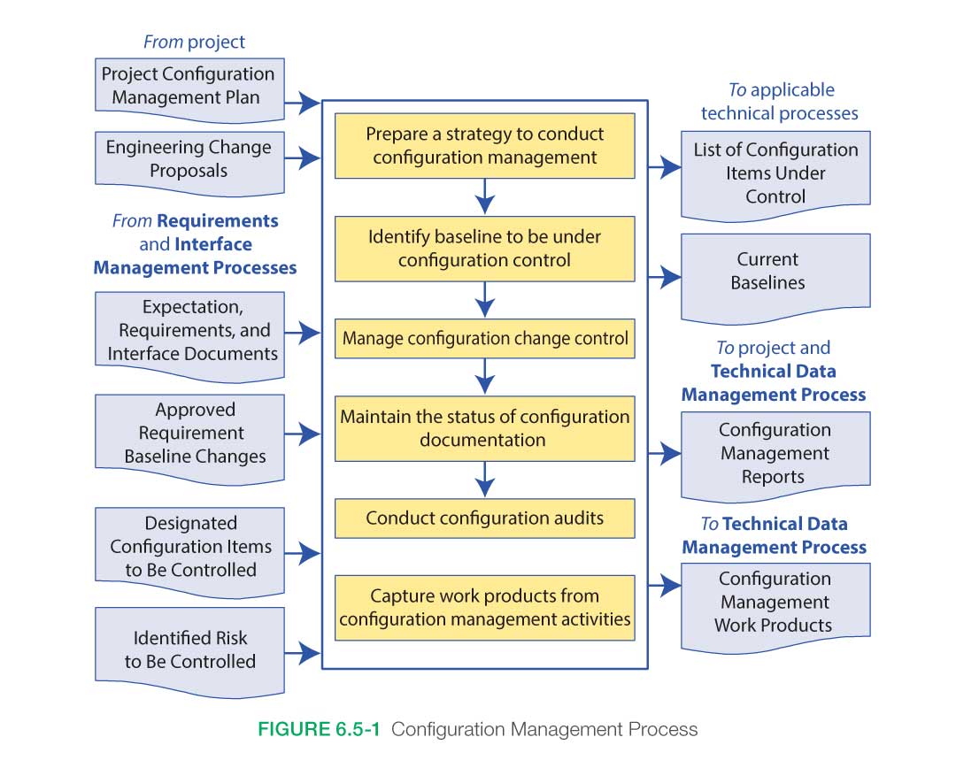
The NASA Configuration Management Process image captures the central idea: identify what is controlled, establish baselines, control changes, maintain status, audit the result, and retain work products.
Establish scope and responsibility before creating files
The first controlled object should be a concise Project Quality and Configuration Charter. Create one for the ECU housing now, then reuse its structure for the door trim and HVAC outlet.
Use this identifier:
EDV-SIM-ECU-PQC-001 Rev A
Its purpose is not to repeat every technical requirement. It establishes the operating boundary of the project.
Minimum charter content
| Charter field | Simulated ECU example |
|---|---|
| Project scope | Injection-molded high-voltage ECU enclosure assembly: base, cover, gasket, inserts, fasteners, vent concept, PCB support features, and mounting interfaces |
| Customer context | Rivian-built Amazon Electric Delivery Van context, explicitly assumption-based unless supported by a controlled public source |
| Target market | “United States market assumed pending controlled customer confirmation” |
| Design-responsibility status | Design responsible for enclosure geometry and integration assumptions; supplier responsible for its manufacturing-process design unless separately delegated |
| Key interfaces | Vehicle mounting structure, electrical connectors, PCB, harness, gasket supplier, injection molder, test laboratory |
| Quality objectives | Requirements baseline approved before detailed CAD; all release requirements traceable to verification evidence; no open high-severity launch risk without documented gate disposition |
| Applicable-source register | Link to the standards register from the previous lesson |
| Records location | Onshape document links plus controlled project workbook and evidence folder |
| Approval roles | Program Manager, Mechanical Design Lead, Quality Lead, Supplier Quality Lead, Validation Lead |
| Assumption boundary | No proprietary Rivian, Amazon, supplier, or vehicle data is represented as fact |
Assign responsibility to roles, not to people’s names
An organization needs named individuals for practical execution, but the responsibility belongs to a role or position. If a Mechanical Design Lead leaves the project, the responsibility must not disappear with that person.
[PDF] International Automotive Task Force IATF 16949:2016
Use the IATF FAQs to establish two important rules for the simulated record: responsibility is attached to a role, and design responsibility depends on how complete the incoming engineering definition is.
On page 4, read FAQ 5 under Clause 5.3.1. Focus on role based authority. Then go to page 23 and read FAQ 25, “8.3 Design and Development of products and services.” Focus on the design responsibility test. Read each answer in full, including the statement that manufacturing-process design remains an organizational responsibility.
For this course, the component concepts are incomplete by design: package dimensions, interfaces, performance targets, and customer expectations are progressively defined through controlled assumptions. Therefore, the simulated engineering organization is product design responsible for the component definition it creates.
That does not mean it owns every activity. A supplier may own tooling design, molding parameters, resin handling, or assembly-fixture design. The project record must show exactly where responsibility starts and ends.
Configure a role-based responsibility matrix
Use a responsibility matrix with one accountable role for each deliverable. “Accountable” means the role accepts the result; “Responsible” means the role performs or coordinates the work.
| Controlled activity | Accountable role | Responsible role | Required consultation |
|---|---|---|---|
| Requirements baseline and RTM | Mechanical Design Lead | Systems/Requirements Engineer | Quality Lead, Validation Lead |
| CAD, drawing, and EBOM definition | Mechanical Design Lead | Design Engineer | Manufacturing Engineer, Supplier Quality |
| Moldability and tooling feasibility | Supplier Quality Lead | Injection-Molding Supplier | Mechanical Design Lead, Tooling Engineer |
| DFMEA | Mechanical Design Lead | Cross-functional DFMEA team | Quality, Manufacturing, Validation |
| PFMEA and Control Plan | Supplier Quality Lead | Manufacturing Supplier | Quality Lead, Manufacturing Engineer |
| DVP&R and test configuration | Validation Lead | Test Engineer | Mechanical Design Lead, Quality Lead |
| Nonconformance containment | Quality Lead | Supplier Quality or Manufacturing Lead | Design Lead, Program Manager |
| ECO approval and release | Program Manager | Change Coordinator | All affected functional owners |
A common failure is assigning “supplier” as the owner of a problem without defining the customer-side owner. Even when the injection molder performs the corrective action, the simulated Supplier Quality Lead remains accountable for supplier escalation, evidence review, and the decision to accept or reject recovery evidence.
Give every controlled object an identity, status, and revision
The record should work whether the team uses a full PLM implementation or a lightweight controlled environment. For this course, use:
- Onshape for CAD, assemblies, versions, and shareable views;
- a controlled spreadsheet or database for the master index, RTM, gate status, and change log;
- a controlled evidence folder for PDFs, supplier records, signed decisions, and test outputs.
Onshape versions help preserve CAD states, but a version by itself is not a complete engineering release. The release record must state what was released, why, under which baseline, and with which approvals.
Recommended identifier scheme
Use stable identifiers. Do not encode too much intelligence in a filename; a short code and a master index are more reliable than a long filename attempting to describe every property.
| Object type | Identifier example | Purpose |
|---|---|---|
| Requirement | REQ-ECU-042 | A uniquely testable requirement |
| Assumption | ASM-ECU-011 | A declared, confidence-rated engineering assumption |
| Interface | ICD-ECU-003 | Controlled interface definition |
| CAD model | CAD-ECU-BASE | Master CAD object with version or revision reference |
| Drawing | DRW-ECU-BASE | 2D definition associated with released CAD |
| EBOM | EBOM-ECU-001 | Engineering product structure |
| Validation plan | DVP-ECU-001 | Verification and validation planning |
| Test report | TEST-ECU-IP-003 | Objective test evidence |
| Supplier record | SUP-ECU-MOLDER-001 | Supplier qualification and performance record |
| Nonconformance | NCR-ECU-007 | Record of a requirement nonconformance |
| Corrective action | CAPA-ECU-004 | Root cause, corrective action, effectiveness evidence |
| Engineering change request | ECR-ECU-005 | Proposal or problem statement requesting a change |
| Engineering change order | ECO-ECU-005 | Approved and implemented controlled change |
| Baseline | BASE-ECU-G2-01 | Frozen set of objects assessed at a gate |
Use a separate revision field such as Rev A, Rev B, or 01, 02. Never change a document’s content without changing the revision or version state that identifies it.
Use a defined maturity model
A simple lifecycle is adequate for the simulated program:
| Maturity state | Meaning | May it be sent to a supplier? |
|---|---|---|
| Work in Progress | Being developed; not approved for decisions | No, unless explicitly marked as an unapproved feasibility discussion |
| In Review | Submitted for formal review | Only with review status clearly visible |
| Approved | Content accepted for its stated purpose | Yes, for the approved purpose only |
| Released | Baseline-controlled definition authorized for use | Yes, as controlled technical data |
| Superseded | Replaced by a newer released item | No for new work; retain for history |
| Archived | Retained record with restricted use | No |
The distinction between approved and released matters. A DFMEA may be approved for G2 feasibility review, while the production drawing is not released until its associated requirements, GD&T plan, material, verification status, and change impacts meet the release criteria.
Map the record to CATIA and ENOVIA concepts
| Simulated course control | Onshape implementation | Typical CATIA/ENOVIA concept |
|---|---|---|
| Product structure | Assembly plus BOM export or controlled BOM table | CATIA Product structure managed as ENOVIA items |
| Component definition | Part Studio and derived parts | CATIA Part with Part Design and GSD features |
| Controlled interface | Named mate connectors, reference geometry, exported interface data | Published elements and controlled interface objects |
| CAD snapshot | Onshape Version | CATIA revision or version under PLM management |
| Formal release | Release workflow if available, plus signed release record | ENOVIA lifecycle promotion and release workflow |
| Design record | Drawing PDF, model link, material and specification references | ENOVIA-managed document linked to the item |
| Change control | ECR/ECO log with linked Onshape versions | ENOVIA Change Action, Change Order, and implementation records |
Exact ENOVIA object names and workflows vary by company configuration. The mapping is conceptual: an authoritative item, a controlled document, a revision, a lifecycle state, a baseline, and an approved change must be connected.
Control supplier interfaces and build a traceability plan
The supplier interface is more than a purchase order. For an ECU enclosure, the injection molder, gasket supplier, insert supplier, coating provider if used, and test laboratory can all affect conformity.
The project record must preserve the technical agreement that each supplier is working to: the required product definition, special characteristics where justified, required evidence, applicable material or regulatory evidence, change-notification rules, and acceptance method.
This section connects supplier control with traceability. Read it to see why supplier qualification, the extent of incoming control, and the ability to isolate suspect product all belong in the same project record.
On pages 37–40, read Clause 8.4 from “Control of Externally Provided Processes, Products and Services” through 8.4.3, “Information for external providers.” Focus on external provider control, then continue through the discussion of supplier selection, monitoring, and communicated requirements. Next, go to page 43 and read Clause 8.5.2, “Identification and traceability,” in full. Focus on risk based traceability. Notice that traceability must support quick identification and segregation of suspect product.
Create a Supplier and Interface Control Matrix
Create SICM-ECU-001 Rev A. One row should exist for every supplier relationship or external technical service that can affect product conformity.
| Field | Injection-molding supplier example |
|---|---|
| Supplier and manufacturing site | SUP-ECU-MOLDER-001; site pending qualification |
| Supplied scope | Molded PA66-GF30 ECU base and cover |
| Supplier responsibility | Tool design, molding-process development, dimensional control, lot traceability, PFMEA, Control Plan, process capability evidence |
| Internal responsibility | Released design definition, functional requirements, DVP&R ownership, supplier approval, disposition authority |
| Controlled inputs to supplier | Released CAD, drawing, material specification, special-characteristic list, packaging requirements, approved deviations |
| Supplier deliverables | DFM report, tooling feasibility, resin certificate, lot records, dimensional report, mold-flow evidence, PPAP-readiness evidence |
| Verification method | Receiving inspection plan, dimensional review, supplier audit as risk warrants, validation testing |
| Required traceability | Resin batch, molding lot, cavity where relevant, tool ID, production date, inspection status |
| Change rule | Supplier cannot change resin source, mold, tool location, processing strategy, inspection method, or manufacturing site without documented notification and approved disposition |
| Escalation route | Supplier Quality Lead, Quality Lead, Program Manager; customer notification only where the actual customer requirement requires it |
For safety- or compliance-relevant components, use a stricter level of traceability. The course’s HV ECU context may contain electrical-isolation and sealing requirements, but do not label a characteristic “safety critical” casually. The classification must come from an approved requirement, risk analysis, and applicable standard or customer direction.
The traceability chain for the ECU housing
A useful record is not a list of links added after the work is done. Build the links as work progresses.
| Starting object | Linked evidence |
|---|---|
REQ-ECU-042: ingress performance | Sealing concept, gasket specification, DVP&R entry, test procedure, test report, NCRs, ECOs |
CAD-ECU-BASE Rev B | Onshape version link, drawing DRW-ECU-BASE Rev B, draft-analysis output, DFMEA references, tool feasibility feedback |
| Gasket material lot | Supplier certificate, incoming receipt, assembly build record, test-unit configuration |
Test unit TU-ECU-IP-03 | Base and cover revisions, gasket lot, fastener torque procedure, laboratory, equipment calibration status, test report |
NCR-ECU-007: warped sealing land | Contained production lots, measurement data, supplier 8D, updated PFMEA, ECR/ECO, revalidation result |
This level of traceability is not bureaucracy for its own sake. If a leak test later fails, the team should be able to distinguish a design problem, a molding-lot problem, a gasket installation problem, a test-fixture problem, or a test-procedure problem without reconstructing history from email.
Make validation evidence configuration-specific
Validation is persuasive only when the tested article is known. A report saying “ECU enclosure passed ingress testing” is weak unless it also says what enclosure was tested.
For every DVP&R entry, configure these fields:
| Field | Why it matters |
|---|---|
| Requirement ID and acceptance criterion | Prevents a test from becoming a generic activity without a pass/fail basis |
| Verification method | Test, analysis, inspection, or demonstration |
| Test procedure and revision | Shows how the evidence was generated |
| Test article configuration | Links CAD/drawing revisions, material grade, supplier, lots, assembly state, and relevant software or firmware where applicable |
| Instrument and calibration reference | Establishes confidence in the measurement |
| Conditioning and environment | Makes results comparable and repeatable |
| Result and disposition | Pass, fail, conditional pass, or invalid test — not merely “completed” |
| Deviation reference | Makes departures from the plan visible |
| Approval | Identifies the role accepting the evidence |
A failed test is not automatically an ECO. First identify what failed:
- If the unit does not meet the current released requirement, create an NCR.
- If the requirement itself is unclear, contradictory, or infeasible, create a requirements issue and likely an ECR.
- If an approved design, process, or control must change, create an ECO after impact analysis.
- If the test setup was invalid, retain the invalid result and document why a retest is needed. Do not quietly overwrite the evidence.
At G4, your simulated program will prepare a PPAP-readiness package, not a real customer PPAP approval. The project record should still link the expected evidence: released design record, authorized engineering changes, DFMEA, process flow, PFMEA, Control Plan, material and dimensional evidence, validation results, measurement-system evidence, and submission disposition.
Control nonconformance without confusing it with design change
A nonconformance is a failure to meet a specified requirement. It can involve a physical part, CAD output, drawing, process, document, supplier certificate, test result, or inspection method.
A well-configured nonconformance record should prevent unintended use of suspect material while enabling disciplined technical disposition.
Read these clauses to distinguish two connected but different systems: controlling a planned change, and controlling product or outputs that do not conform to current requirements.
On pages 45–46, read Clause 8.5.6, “Control of changes,” including 8.5.6.1. Focus on change review and validation. Then read page 47 through the first paragraph of page 48 under Clause 8.7, “Control of Nonconforming Outputs.” Focus on containment and disposition. Finally, read the concession paragraph and note the limits of concession.
Configure an NCR workflow
Create NCR-ECU-007 for any simulated issue that represents a requirement nonconformance. Use the following states:
- Detected and contained — identify affected parts, documents, lots, test units, and shipments; stop unintended use.
- Characterized — define the nonconformance against the exact requirement, including measurement method and evidence.
- Disposition proposed — options may include rework, scrap, return to supplier, use under approved concession, or further technical evaluation.
- Disposition approved — approval authority is recorded. A supplier cannot authorize itself to deviate from a released customer requirement.
- Root cause and corrective action — use an appropriate method, such as 5-Why or 8D, when the issue warrants it.
- Effectiveness verified — demonstrate that correction worked and recurrence controls are active.
- Closed — all affected records, FMEAs, Control Plans, validation plans, and change records have been reviewed.
NCR, concession, corrective action, and ECO are different records
| Record | Purpose | Does it change the released definition? |
|---|---|---|
| NCR | Records a failure to meet the current requirement | No |
| Concession or deviation permit | Authorizes a limited, controlled departure from the current requirement | No; it is temporary and bounded |
| Corrective action / 8D | Removes or reduces the cause of an identified nonconformance | Not necessarily |
| ECR | Requests evaluation of a possible permanent change | No |
| ECO | Approves and implements a permanent controlled change | Yes |
For example, suppose prototype ECU covers show sealing-land flatness outside the current drawing requirement:
- The NCR identifies the affected covers and prevents their normal use.
- A temporary concession might permit carefully selected prototype parts for a limited non-safety-related learning build, but only if the authorized roles accept the risk and the scope is documented.
- The supplier’s corrective action may adjust molding parameters or investigate tooling deformation.
- An ECO is needed only if the team changes the design, mold, drawing, material, process control, acceptance criterion, or other controlled baseline.
Configure engineering-change control as an impact-assessment system
An ECO is not simply a revised CAD file. It is the record that answers why the configuration changed, what else is affected, who approved the new state, how it was verified, and when the old state ceased to be valid.
Use two linked objects:
- ECR — captures the issue, opportunity, supplier proposal, or customer request.
- ECO — the authorized implementation package once impact analysis and approvals are complete.
Required ECO fields
| ECO field | ECU example |
|---|---|
| Change reason | Supplier reports recurring sealing-land distortion near a gate location |
| Affected baseline | BASE-ECU-G3-01 |
| Affected objects | Base CAD, base drawing, mold-flow study, DFMEA, PFMEA, Control Plan, DVP&R, EBOM/MBOM, PPAP-readiness index |
| Proposed action | Relocate gate and locally revise rib pattern to reduce distortion |
| Technical rationale | Mold-flow and dimensional evidence indicate a plausible fill-and-packing contribution to warpage |
| Risk impact | Sealing performance, tooling timing, dimensional capability, validation schedule, stock disposition |
| Required verification | Updated mold-flow assessment, dimensional trial, gasket-compression stack review, repeat ingress validation |
| Supplier impact | Tool modification, revised process documentation, revised pre-launch controls, trial-run evidence |
| Approval roles | Mechanical Design Lead, Quality Lead, Supplier Quality Lead, Validation Lead, Program Manager |
| Implementation point | Defined tool trial and effective lot or date |
| Old-stock disposition | Quarantine, prototype-only use under approved deviation, rework, or scrap, as applicable |
| Closure evidence | Revised objects released; required verification passed; affected baseline and gate status updated |
The ECO sequence
- Initiate and contain the trigger. Link the supplier issue, NCR, test failure, customer request, or improvement proposal.
- Assess impact before approval. Review requirements, standards applicability, interfaces, CAD, drawings, EBOM, manufacturing view, FMEAs, Control Plans, supplier tooling, validation, and PPAP-readiness evidence.
- Define the implementation and verification plan. State exactly what must be tested, inspected, or analyzed before release.
- Obtain role-based approvals. Approvals must reflect authority, not merely attendance in a meeting.
- Implement the new configuration. Release revised CAD, drawing, BOM, supplier data, process controls, and instructions together where applicable.
- Control the cut-in. Record the effective date, lot, serial range, build phase, or tool state. Preserve traceability of material produced during transition.
- Verify and close. Confirm that the changed configuration meets requirements and that all linked records are updated.
A temporary alternate inspection or process control should not become an invisible permanent workaround. If it is used, identify the affected product, record the risk basis and approval, monitor the temporary condition, and return to the standard control or formally revise the controlled process.
Build the minimum viable ECU project record
Set up the following controlled structure now. It is intentionally lightweight enough for Onshape plus templates, but complete enough to resemble a company project record.
EDV-SIM-ECU/
  00_Governance/
    EDV-SIM-ECU-PQC-001_Project_Quality_Configuration_Charter
    Roles_and_Responsibility_Matrix
    Assumptions_Log
    Standards_Register_Link
    Gate_Decision_Log

  01_Requirements_and_Interfaces/
    Requirements_Traceability_Matrix
    Interface_Control_Matrix
    Packaging_and_Keepout_Assumptions

  02_Product_Definition/
    Onshape_CAD_Links_and_Versions
    Drawings
    EBOM
    Proposed_MBOM_View
    Material_and_Joining_Records

  03_Risk_and_Quality_Planning/
    Risk_Register
    DFMEA
    DVP_and_R
    Prototype_Control_Plan
    Supplier_and_Interface_Control_Matrix

  04_Verification_and_Validation/
    Analysis
    Test_Procedures
    Test_Reports
    Inspection_Reports
    Test_Article_Configuration_Log

  05_Supplier_Records/
    Supplier_Qualification
    DFM_and_Tooling_Feedback
    Material_and_Lot_Certificates
    Supplier_8D_and_CAPA

  06_Nonconformance_and_Change/
    NCR_Log
    Concessions_and_Deviations
    ECR_Log
    ECO_Log
    Released_Baselines

  07_Release_and_Gates/
    G1_G2_G3_G4_Packages
    PPAP_Readiness_Index
    Approval_Evidence
Then create a one-page Master Record Index with these fields:
| Field | Purpose |
|---|---|
| Object ID | Stable identifier |
| Object title | Human-readable name |
| Object type | Requirement, CAD, test report, NCR, ECO, and so on |
| Revision/version | Exact controlled state |
| Maturity state | Work in Progress, In Review, Approved, Released, Superseded |
| Owner role | Accountable role |
| Storage location | Onshape link or controlled file path |
| Related baseline | Gate or release baseline |
| Parent links | Requirements, interfaces, supplier, validation, NCR, or ECO links |
| Approval reference | Decision record and approving role |
| Retention/status note | Current, superseded, archived, or restricted |
Your first usable baseline can be:
BASE-ECU-G1-01
Include the approved requirements baseline, assumptions log, standards register, preliminary EBOM, interface-control matrix, risk register, DVP&R outline, and G1 decision record. That baseline is the controlled starting point for detailed ECU design in the next modules.
Key takeaways
An IATF-aligned simulated project record is an evidence architecture, not a collection of files. It should make seven controls visible:
- Design responsibility is explicit, role-based, and distinguished from supplier process responsibility.
- Supplier interfaces define controlled inputs, required outputs, verification, traceability, and change-notification expectations.
- Traceability links requirements, product configuration, suppliers, lots, validation evidence, nonconformances, and changes.
- Documented information has identifiers, revision control, maturity states, approval evidence, and retrievable history.
- Validation evidence identifies the exact tested configuration and acceptance criterion.
- Nonconformance control contains and dispositions deviations from the current requirement without silently changing the definition.
- ECO control assesses and verifies the complete impact of a permanent change before release and tracks its implementation boundary.
Next, you will construct the assumption-based Rivian-built Amazon EDV context and packaging model. That work will populate the project record with confidence-rated vehicle facts, engineering assumptions, keep-out zones, and explicitly owned interfaces.
Can't find a good explanation? Sign up and we'll make it for you
Sign up