
Welcome to the next lesson in our deep dive into injection molding. In our last session, we established the "golden rules" for designing the intrinsic features of a part—applying correct draft and designing stable ribs. We now have a part that is geometrically sound and respects the fundamentals of manufacturability. However, even the most perfectly designed part will fail if the molten plastic cannot enter the mold cavity correctly.
Today, we address the critical decision of how and where to introduce that material. This is the science and art of gate selection. Your choice of gate type and location is one of the most influential decisions you will make, directly impacting cosmetic appearance, structural integrity, cycle time, and cost. This is a responsibility you will share with the tooling engineer, but as the part designer, you must define the requirements and constraints.
By the end of this lesson, you will be able to select an appropriate gate type and location for a given automotive part geometry, justifying your decision based on established engineering principles.
The 'Where': Principles of Gate Location
Before selecting a specific type of gate, you must first understand the principles that govern where a gate should be placed. The location is not arbitrary; it follows four fundamental rules that dictate how the part fills, cools, and performs.
An incorrect gate location can undo all the careful work you put into draft and rib design, leading to the very defects we've sought to avoid.
How to Select the Correct Gate Location - The Madison Group
This article from The Madison Group is an excellent, concise summary of the core principles for gate location. It provides the "why" behind the rules.
Read the article from the beginning, focusing on the four main sections: Thick to Thin: Pay close attention to the reasoning related to packing pressure and the prevention of sink marks and voids. This directly builds on our last lesson. Unidirectional Flow: Understand how a balanced, unidirectional flow path improves mechanical properties by aligning polymer molecules. Air Trapping: Note the connection between gate location, flow front progression, and the ability to vent trapped air at the parting line to prevent burn marks. Pressure to Fill: Grasp the relationship between flow length and the injection pressure required.
Let's summarize these four critical rules:
- Gate from Thick to Thin: Always gate into the thickest cross-section of the part. This ensures the gate remains molten longer than the thinner sections, allowing the packing phase to effectively push additional material into the thick areas as they shrink, counteracting sink marks and voids.
- Promote Unidirectional Flow: Position the gate to create a single, advancing flow front that fills the cavity progressively. This avoids "race-tracking" (where plastic flows much faster down a thick channel) and ensures more uniform polymer orientation and lower internal stress, reducing warpage.
- Control Weld Lines and Venting: The gate location dictates where separate flow fronts will meet, forming weld lines. You must position the gate to move these weld lines away from structurally critical or cosmetic A-class surfaces. A well-placed gate also pushes air towards the parting line or dedicated vents, preventing trapped air and burn marks.
- Minimize Flow Length: A shorter path from the gate to the furthest point of the cavity means lower injection pressure is needed. This reduces residual stress in the part, consumes less energy, and allows for a wider processing window.
As a designer, you will often use mold flow simulation software (e.g., Moldflow, Moldex3D) to verify these principles. This software predicts exactly how the plastic will fill the cavity for a given gate location.
The video below explains the concept of flow length and how simulation helps optimize it.
The 10 Commandments of Injection Molding
This segment from EastWestMfg's "The 10 Commandments of Injection Molding" introduces the concept of flow length ratio and the use of mold flow analysis.
Watch the section from calculating flow length. This will formalize the idea of minimizing the flow path.
The 'How': Types of Injection Molding Gates
Once you have identified potential locations for the gate, you must select the appropriate type. Gates are broadly classified into two categories based on how the part is separated from the runner system:
- Manually Trimmed Gates: These are located on the parting line of the mold. An operator must manually cut or break the part from the runner after molding. They are simpler to machine into the tool but add labor cost to each part.
- Automatically Trimmed Gates: These use clever geometry (or a more complex mold structure) to shear the gate from the part automatically as the mold opens or during ejection. They are ideal for high-volume, automated production.
The image below gives a quick visual overview of the geometry of several common gate types.
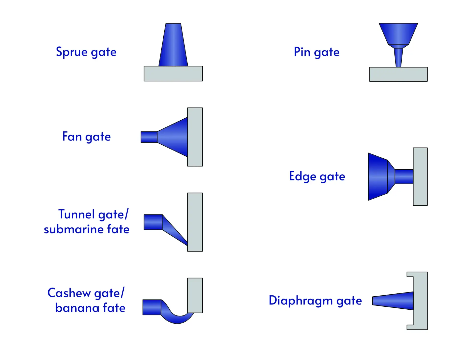
Now, let's explore the most common types used in automotive design.
Injection Molding Gate Advanced Tips | Gate Types & Position
This guide from Firstmold provides a detailed breakdown of various gate types, complete with their advantages, disadvantages, and typical applications.
Read the section "Types of Injection Molding Gate," starting from the "Direct Gate / Sprue Gate" and ending after the "Tab Gate." As you read, focus on understanding the pros and cons of each. Don't worry about memorizing every detail; aim to grasp the primary use case for each type.
To consolidate this information, here is a summary of the gates most relevant to automotive trim and BIW applications:
| Gate Type | Degating | Mold Type | Typical Automotive Use | Key Consideration |
|---|---|---|---|---|
| Edge Gate | Manual | 2-Plate | General purpose, non-cosmetic edges of brackets, enclosures. | Simple and cheap, but leaves a visible vestige and requires labor. |
| Fan Gate | Manual | 2-Plate | Large, flat parts like door panel substrates or load floors. | Spreads flow to prevent warpage and "jetting" across a wide front. |
| Tab Gate | Manual | 2-Plate | Shear-sensitive materials (e.g., PC, PMMA) for lenses or clear panels. | The tab absorbs the high shear stress, protecting the part surface. |
| Pin Gate | Automatic | 3-Plate or Hot Runner | Allows gating on the B-surface of a cosmetic part (e.g., center console side panel). | Flexible location but requires a more complex and expensive mold. |
| Submarine Gate | Automatic | 2-Plate | High-volume production of small-to-medium parts; hides gate on non-cosmetic feature. | Excellent for automation and hiding vestiges. Can be difficult to process with filled materials. |
This image shows a submarine gate, a very common choice for automated production, feeding two parts in a multi-cavity tool.

The Decision-Making Process: A Synthesis
You now have the tools to decide both where and how to gate a part. The final selection is a synthesis of part requirements, material properties, and cost targets.
The following video provides an excellent case study comparing two different gating strategies for a cup holder and analyzing the results using mold flow simulation.
How Do Gates Affect Part Quality? |Gate Design Series |Thermoplastic Injection Molding Simulation
This video from The Madison Group, "How Do Gates Affect Part Quality?", ties together all the concepts we've discussed.
Watch the entire video (full video). It serves as a perfect summary, covering: The function of a gate. An overview of different gate types. The principles of gate placement (thick-to-thin, weld lines). A practical simulation example comparing a pin gate and an edge gate.
Your Role as a Design Engineer
As the design engineer, your primary responsibility is to define the allowable gating zones. You will not typically design the final gate and runner geometry—that is the toolmaker's expertise. However, you must communicate your constraints.
In CATIA, you would do this by creating a specific surface or publication on your PartBody named ALLOWABLE_GATING_ZONE. You would place this surface on a non-cosmetic, B-side area, ideally in a thick region where a gate vestige is acceptable. This explicitly tells the mold designer where they are permitted to gate the part. You must defend this choice during design reviews, explaining how it adheres to the principles we've discussed.
Conclusion
Gate selection is not an afterthought; it is a core DFM consideration that you must address early in the design process. An intelligent gating strategy is the gateway to a high-quality part, while a poor one is a direct path to scrap, delays, and cost overruns.
Key Takeaways:
- Gate Location Principles: Always gate from thick-to-thin sections to ensure proper packing. Position the gate to create a unidirectional flow, minimize flow length, and place weld lines in non-critical areas.
- Gate Type Selection: The choice of gate type is a trade-off between mold complexity (cost), automation potential, and cosmetic requirements. Edge gates are simple, while submarine and pin gates allow for automation and hidden blemishes.
- Engineer's Responsibility: Your role is to analyze the part's functional and cosmetic requirements and define an "allowable gating zone" for the toolmaker, backed by sound engineering principles.
In our next lesson, we will shift focus from manufacturing principles to documentation. We will begin building the foundation for a professional 2D drawing by learning how to define datums and establish a datum reference frame (DRF). This is the first and most critical step in applying GD&T to control part geometry.
Can't find a good explanation? Sign up and we'll make it for you
Sign up