
In our last lesson, we diagnosed the common ailments of injection molded parts, from sink marks to warpage. Today, we move from diagnosis to prevention. Think of this lesson as the design engineer's pharmacopeia—a collection of "golden rules" that, when applied correctly in CAD, will prevent those manufacturing defects from ever occurring.
Your ability to internalize these rules is what separates a novice designer from an experienced one. This isn't just about making a part that looks right on screen; it's about designing a part that can be molded efficiently, repeatably, and economically, millions of times over. We will focus specifically on applying rules for draft angles, especially for textured surfaces common in automotive interiors, and defining the correct relationship between ribs and the walls they support.
The Foundation: Uniform Wall Thickness
Before we get into specific features, the cardinal rule that governs almost everything else is to maintain a uniform wall thickness throughout the part. As you recall from our discussion on defects, differential shrinkage is the primary cause of warpage, and thick sections are the cause of sink marks. Striving for constant wall thickness is your primary defense against both.
The RAPID DIRECT video below gives a quick overview of this principle and a typical thickness range for many parts.
Injection Molding Design Tips - 10 DFM Guidelines
This segment from "Injection Molding Design Tips" introduces the concept of nominal wall thickness.
Watch the section on wall thickness. Note the recommended range and the consequences of deviating from it.
In automotive design, a nominal wall thickness of 2.5mm to 3.0mm is a common target for interior trim and non-structural components. Your goal is to adhere to this nominal value wherever possible. But what happens when you need to add features like vertical walls or stiffeners? That's where the next rules come into play.
Rule 1: Apply Sufficient Draft
For a part to be ejected from the mold, its vertical walls cannot be perfectly vertical. They must be angled slightly. This angle is called draft. Without it, the part will drag against the highly polished steel mold, causing scratches (drag marks), and the high friction can lead to part warping or even damage to the mold during ejection.
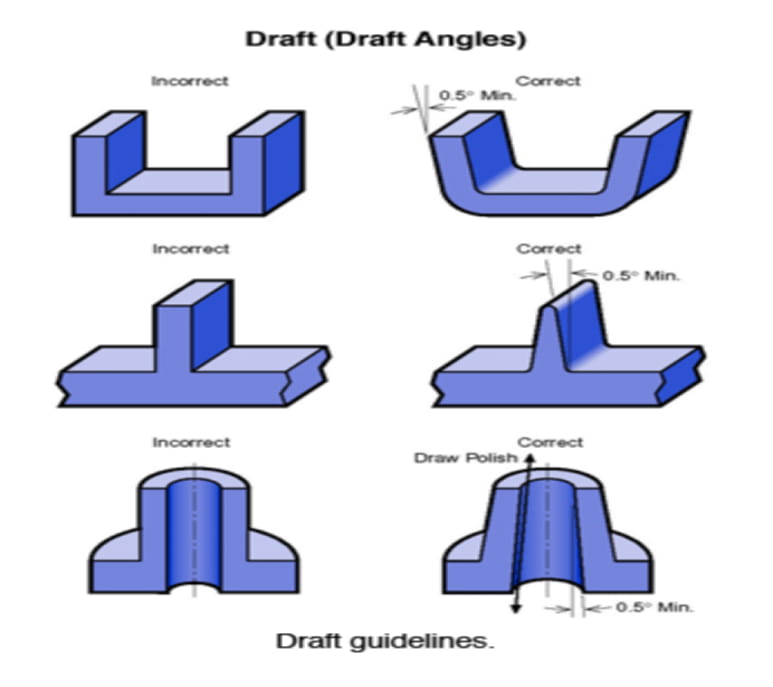
To understand the importance of draft from a manufacturing perspective, watch the following video.
Injection Molding - Draft Angle (Why and How to Design)
The video "Injection Molding - Draft Angle" by Protolabs provides an excellent physical demonstration and explanation of why draft is non-negotiable.
Watch the first two main segments of the video: What is draft? This section explains the fundamental purpose of draft angles. Design considerations. Pay close attention to the discussion on texture. This is critical for automotive interior components.
Draft Angle Rules of Thumb
As you just saw, the amount of draft required is not a single number. It depends on the surface finish, material, and depth of the feature. Here are the "golden rules" you must commit to memory:
- Baseline: Start with a minimum of 1° to 2° of draft on all surfaces parallel to the mold's direction of pull.
- Polished Surfaces: For smooth, "Class A" surfaces with a mirror-like polish, you might get away with as little as 0.5°, but this increases tooling risk.
- Textured Surfaces (The Texture Tax): This is where many designs fail. Textured surfaces, like the grain on a dashboard or door panel, have microscopic undercuts. The plastic flows into these tiny pits and valleys, creating much more friction. To overcome this, you must add more draft.
- The Rule: A standard industry guideline is to add 1° to 1.5° of draft for every 0.001 inch (or ~0.025 mm) of texture depth.
- A light texture (e.g., VDI 24) might require 3° of draft.
- A heavy leather grain (e.g., VDI 33) could require 5° or more.
The following article provides a highly detailed, field-tested set of rules for applying draft. This is the level of detail expected in an automotive design review.
Mastering Injection Molding Draft Angle: Avoid Costly Mistakes
This article from PTSMAKE codifies decades of molding experience into actionable rules. It moves beyond simple recommendations to a decision matrix and unbreakable laws.
Read the following two sections carefully: Start with "The Draft Angle Decision Matrix." Analyze the table that considers Surface Finish, Part Depth, and Material Shrinkage. This is how you justify your draft angle choice. Then, focus on the section "What is the Draft Angle Rule?" and specifically memorize "The 5 Unbreakable Draft Laws." These are your golden rules, especially the "25:1 Ratio" and the "Texture Tax."
In CATIA, you would apply this using the Draft Angle feature within the Part Design workbench. You must define three key inputs: the faces to be drafted, the angle, and a "pulling direction," which corresponds to the direction of mold ejection.
Rule 2: Design Proper Ribs and Bosses
To add strength and stiffness to a part without violating the uniform wall thickness rule, we use ribs. However, a poorly designed rib will cause the very defect we try to avoid: a sink mark.
The key is the rib-to-wall thickness ratio.
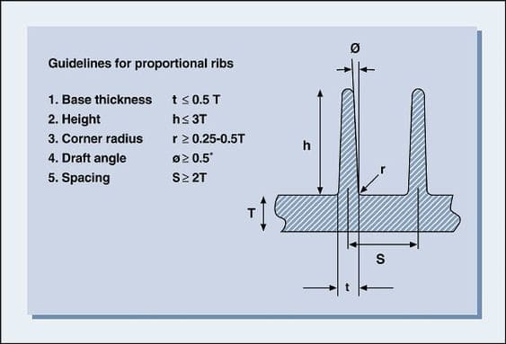
Let's break down the rules shown in that diagram and supplement them with industry standards.
Rib Design Rules of Thumb
- Rib Thickness: The thickness of the rib at its base (
tin the diagram) should be 50-60% of the nominal wall thickness (T). This is the single most important rule to prevent sink marks. If your wall is 2.5mm, your rib should be no more than 1.5mm thick at its base. - Rib Height: Rib height (
h) should be no more than 3 times the nominal wall thickness. Taller ribs can cause filling issues and may be difficult to eject. - Rib Spacing: The distance between ribs (
S) should be at least 2 times the nominal wall thickness. Placing them too close can create cooling problems and warp. - Draft: Ribs are tall, thin features. They require draft, typically a minimum of 0.5° to 1° per side.
- Base Radius: Use a generous radius (
r) at the base of the rib, typically 25-50% of the nominal wall thickness, to avoid stress concentration. Never leave a sharp corner.
The video below provides a quick summary of the rib thickness rule.
Injection Molding Design Tips - 10 DFM Guidelines
This segment from "Injection Molding Design Tips" reinforces the "golden rule" for rib thickness.
Watch the section on ribs and gussets. The 60% rule is explicitly mentioned here.
For a more comprehensive guide on designing both ribs and the bosses they often support, refer to the following resource.
Mastering Plastic Part Design: Key Principles & Tips - ptsmake
This article from PTSMAKE provides detailed, tabulated data for designing structural features like ribs and bosses, aligning perfectly with automotive standards.
Read the following two sections: Under the heading "What are design guidelines for injection molding plastic parts?", find the sub-heading "Rib and Boss Design." Study the bulleted list of guidelines for thickness, height, spacing, and radius. Under the heading "What role do ribs and bosses play in plastic parts?", review the table under "Material Flow and Thickness Guidelines." This table clearly shows the recommended thickness percentages for ribs, bosses, and gussets relative to the main wall.
In CATIA, you would typically model ribs using a sketched profile and the Pad command, then add fillets at the base and apply draft to the side faces. While a Rib or Stiffener feature exists, creating it manually gives you more precise control over these critical geometric ratios.
Conclusion
This lesson has armed you with the fundamental rules of DFM for injection molding. These are not suggestions; they are requirements for producing high-quality, cost-effective parts. Violating them leads directly to the defects we discussed previously and will cause significant delays and cost overruns in a real-world project.
Key Takeaways:
- Uniform Wall Thickness: This is the master rule that prevents warpage and sink marks.
- Draft Angles: Essential for part ejection. A baseline of 1-2° is standard, but this must be increased for textured surfaces (e.g., 1.5° per 0.025mm of texture depth) and deep features.
- Rib-to-Wall Ratio: To add strength without causing sink, a rib's thickness should be 50-60% of the adjoining wall. Rib height should be limited to ~3x the wall thickness.
- Generous Radii: Always fillet the base of ribs and bosses to reduce stress concentration.
In our next lesson, we'll address another critical design choice that profoundly impacts part quality and mold complexity: selecting an appropriate gate type and location. Understanding how molten plastic enters the cavity will complete our foundational knowledge before we begin designing our first component.
Can't find a good explanation? Sign up and we'll make it for you
Sign up