
In our previous lesson, we focused on ensuring a part's manufacturability by correctly selecting the gate type and location for injection molding. We established how to get molten material into the mold effectively. Now, we must shift our focus to an equally critical question: once the part is made, how do we verify that it is correct? This is where Geometric Dimensioning and Tolerancing (GD&T) begins.
This lesson introduces the absolute foundation of GD&T: the Datum Reference Frame (DRF). Before we can control the location or form of any feature, we must first establish a stable, unambiguous coordinate system for the part itself. This framework is the origin from which all measurements are taken and all tolerances are referenced.
By the end of this lesson, you will be able to define what datums are and establish a primary, secondary, and tertiary (A-B-C) datum reference frame for a simple part, anchoring your selection in the part's function.
The Foundation: What is a Datum Reference Frame?
In manufacturing, we deal with real, imperfect parts. GD&T bridges the gap between the perfect world of CAD and the reality of the shop floor by using a system of theoretical references. The most fundamental of these is the Datum Reference Frame (DRF).
Think of the DRF as a perfect, theoretical 3D coordinate system (X, Y, Z axes and origin) that we lock onto a physical part. This ensures that everyone—the designer, the manufacturer, the quality inspector—measures the part from the exact same starting point, in the exact same orientation.
To build this frame, we must first define some key terms.
Mastering GD&T - Building Datum Reference Frames - Five Flute
This article from Five Flute provides clear, standard definitions for the core concepts we'll be discussing.
Read the section "Basic Terminology and Definitions". Focus on the distinction between: Datum: The theoretically exact plane, axis, or point. Datum Feature: The real, physical surface or feature on your part that you select.
To summarize: we select a physical datum feature on the part (e.g., a mounting face). This imperfect surface is used to create a corresponding, theoretically perfect datum (e.g., a perfect plane). Three of these datums, mutually perpendicular, form the Datum Reference Frame.
Constraining the Part: The Six Degrees of Freedom
Any rigid body floating in space can move in six fundamental ways, known as the Six Degrees of Freedom (6-DOF):
- Three Translations: Moving along the X, Y, and Z axes.
- Three Rotations: Rotating about the X, Y, and Z axes (often denoted U, V, and W).
The entire purpose of a DRF is to systematically lock down all six of these degrees of freedom, leaving the part fully constrained and ready for repeatable measurement.
Datum Reference Frame Overview
This video from GD&T Basics provides a concise overview of the DRF and the concept of degrees of freedom.
Watch the introductory segment from the overview. Pay attention to the visual representation of the three translations and three rotations.
Building the DRF: The 3-2-1 Rule and Datum Precedence
The most common method for creating a DRF for a prismatic part (like a bracket or an engine block) is the 3-2-1 rule. This rule defines how we use three datum features in a specific order of precedence to constrain the 6-DOF.
-
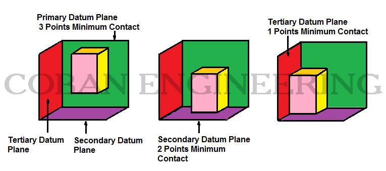
Primary Datum (A): This is the first and most important datum. It's typically the largest, most stable, and most functionally critical surface of the part, such as the main mounting face. The part makes contact with its theoretical datum plane at a minimum of 3 points. This contact locks 3 degrees of freedom (one translation and two rotations).
-
Secondary Datum (B): While held against Datum Plane A, the part is brought into contact with a second theoretical plane, perpendicular to the first. This contact requires a minimum of 2 points. This locks 2 additional degrees of freedom (one translation and one rotation).
-
Tertiary Datum (C): Finally, while held against both A and B, the part is brought into contact with a third plane, perpendicular to the other two. This requires only a minimum of 1 point of contact. This locks the final, 6th degree of freedom (one translation).
The order A, then B, then C is known as datum precedence, and it is critical. It dictates the exact sequence for fixturing the part during inspection.
This animation illustrates precisely how each datum sequentially removes degrees of freedom.
Datum Reference Frame Overview
The "Datum Reference Frame Overview" video will now demonstrate the 3-2-1 rule in action.
Watch the segment from the 3-2-1 rule. Focus on how the part's ability to move is progressively restricted as it contacts Datum A, then B, then C. Note the emphasis on datum precedence.
The image below provides a static summary of this 3-2-1 contact principle.
Reflecting Design Intent
This is the most important concept for you as a design engineer. The DRF must mimic the part's function in its final assembly. The selection of datums is not arbitrary; it's a declaration of design intent.
- Primary Datum (A) should be the feature that makes the most significant connection to the mating part or vehicle body. Where does the part bolt up? What is its primary mounting surface?
- Secondary Datum (B) should be the feature that "clocks" the part or aligns it rotationally. This could be an edge that sits flush against another component, or a hole that aligns with a pin.
- Tertiary Datum (C) is the feature that provides the final locating point.
Changing the datum precedence fundamentally changes the design intent. Imagine a mounting bracket. If Datum A is the face that bolts to the chassis and Datum B is the hole for a locating pin, you are stating that the face-to-chassis connection is more important. If you were to swap them, you would be declaring that the pin location is primary, and the part should pivot around that pin until its face makes contact. This has massive implications for assembly and tolerance stack-up.
The following segment of the video demonstrates this critical concept by swapping the datums on a part and showing how it changes the entire assembly and inspection logic.
Datum Reference Frame Overview
Continuing with the "Datum Reference Frame Overview" video.
Watch the section from changing the intent. This is a critical thinking exercise. Ask yourself: "How does making the cylinder the primary datum instead of the plane change how this part functions and how it would be measured?"
Specifying Datums on a Drawing
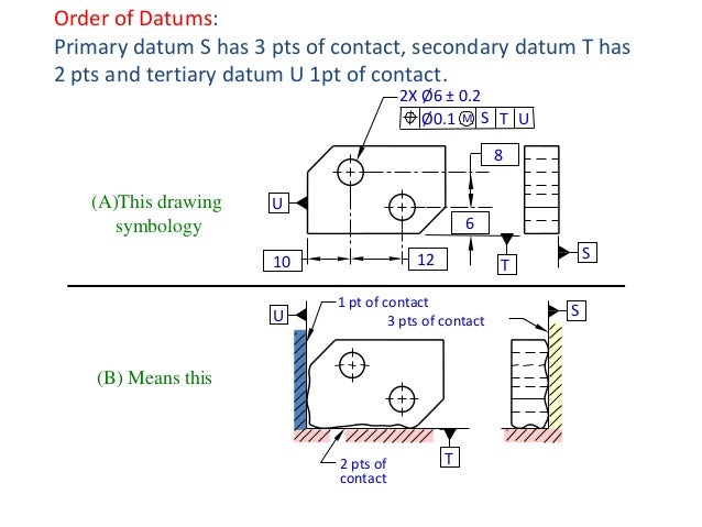
On a 2D drawing, we use the Datum Feature Symbol to identify our chosen datum features. It is a square box containing the datum letter (A, B, C, etc.) with a leader line and a filled or empty triangle pointing to the feature.
The placement of this symbol is precise.
- If the triangle points to a surface, the datum is that surface itself.
- If the symbol is placed in line with a dimension for a feature of size (like a hole or a width), the datum is the centerline or center plane derived from that feature.
Let's look at the practical application.
The following video gives a more detailed walkthrough of how these symbols are applied and interpreted on drawings.
GD&T Lesson 4: Datums & Datum Reference Frame
This video by R. Dean Odell provides a practical guide to identifying datum features on drawings.
Watch the first major section of this video, from identifying datums. Focus on the visual difference between calling out a surface datum versus a center plane/axis datum. This is a common point of confusion, and the explanation here is clear.
Conclusion
You have now learned the fundamental theory behind the Datum Reference Frame. This is the bedrock upon which all other geometric controls are built. Without a properly defined DRF that reflects the part's function, any subsequent GD&T callouts are meaningless.
Key Takeaways:
- A Datum Reference Frame (DRF) is a theoretical 3D coordinate system used to provide a common origin for measurement and inspection.
- The DRF is built by selecting physical Datum Features on the part, which in turn define theoretical Datums (planes, axes, points).
- The 3-2-1 rule describes how a Primary (A), Secondary (B), and Tertiary (C) datum sequentially constrain a part's six degrees of freedom.
- Datum Precedence (the A-B-C order) is critical and must reflect the part's functional requirements and assembly sequence.
In our next lesson, we will build directly on this foundation. Now that we can establish a stable coordinate system for a part, we will learn how to interpret and apply position tolerance to a feature pattern and profile of a surface tolerance to a curved feature. We will define where features must be located relative to the DRF we just created.
Can't find a good explanation? Sign up and we'll make it for you
Sign up