
Welcome back. In our last session, we established the critical foundation of any GD&T scheme: the Datum Reference Frame (DRF). We learned how to use a primary, secondary, and tertiary datum to create a stable, repeatable 3D coordinate system locked to the part, mimicking its assembly and function.
Now that we have this coordinate system, we can begin to control features relative to it. This lesson moves from establishing the origin to defining where features must be. We will focus on two of the most powerful and common controls in automotive design: Position tolerance, which governs the location of features like holes and bosses, and Profile of a Surface tolerance, which controls complex, free-form surfaces.
By the end of this lesson, you will be able to interpret the feature control frames for these tolerances and understand how they are applied to control a pattern of features and a curved surface, respectively.
Position Tolerance: Controlling Feature Location
The Position tolerance is arguably the most frequently used geometric tolerance. It controls the location of a feature of size, such as a hole, pin, or slot, relative to a DRF or other features.
A key concept is True Position: the theoretically exact location of a feature. On a drawing, true positions are defined by basic dimensions, which are numerical values enclosed in a box (e.g., 50.0). These dimensions have no tolerance themselves; the tolerance is specified entirely within the Feature Control Frame (FCF).
Let's watch a video that introduces the concept and its main advantages over traditional +/- tolerancing.
The video "Understanding GD&T" by The Efficient Engineer provides an excellent introduction to Position tolerance.
Watch the segment from the introduction. Pay close attention to two key points: How basic dimensions define the True Position. The difference between a square tolerance zone (from +/- dimensions) and the more functional cylindrical tolerance zone created by a Position tolerance.
As you saw, the cylindrical tolerance zone provides 57% more tolerance area than a square zone for the same deviation along the axes, more accurately reflecting the function of round features like pins in holes.
The Role of Material Condition Modifiers (MMC and LMC)
Position tolerance becomes even more powerful when combined with material condition modifiers. For an automotive engineer, understanding this is non-negotiable as it directly impacts manufacturability and cost. These modifiers allow the specified tolerance to increase as the actual produced size of the feature departs from a specific condition, a concept known as bonus tolerance.
- Maximum Material Condition (MMC - Ⓜ): The state where a feature contains the most material.
- For a hole, this is its smallest allowable diameter.
- For a shaft or pin, this is its largest allowable diameter.
- Least Material Condition (LMC - Ⓛ): The state where a feature contains the least material.
- For a hole, this is its largest allowable diameter.
- For a shaft or pin, this is its smallest allowable diameter.
- Regardless of Feature Size (RFS): The tolerance applies at any produced size. This is the default if no modifier is specified. No bonus tolerance is available.
When MMC is specified, the stated position tolerance applies when the feature is at its MMC size. If the feature is produced away from MMC (e.g., a hole is made larger), a bonus tolerance is gained. This is because a larger hole can be further off-center and still assemble with its mating pin.
Let's continue with the "Understanding GD&T" video to see how these modifiers work.
Watch the explanation from on modifiers. Focus on the example of a hole and understand how the bonus tolerance is calculated when the hole is larger than its MMC size.
The bonus tolerance calculation is straightforward:
- Bonus (Hole) = Actual Hole Size - MMC Hole Size
- Bonus (Pin) = MMC Pin Size - Actual Pin Size
This is a critical tool. It allows manufacturing to use a larger, more forgiving positional tolerance for parts that are not at their worst-case size, reducing scrap and cost without compromising assembly.
Application: A Pattern of Features
Position tolerance is ideal for controlling groups of features, like a bolt pattern on a flange or mounting holes on a bracket. The 4X in front of the dimension indicates the tolerance applies to all four holes in the pattern.
Let's look at a practical example.
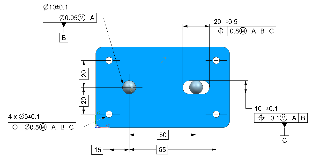
Focus on the callout for the four holes in the top left:4X Ø8.5 - 8.9⌖ | ⌀0.2 Ⓜ | A | B | C
Let's break this down:
4X Ø8.5 - 8.9: This specifies four holes, each with a diameter between 8.5mm and 8.9mm.⌖: This is the symbol for Position tolerance.⌀0.2 Ⓜ: This defines the tolerance zone. It is a cylindrical zone (⌀) with a diameter of 0.2mm. This tolerance applies at Maximum Material Condition (Ⓜ).A | B | C: This specifies the Datum Reference Frame. The True Position of the holes is established relative to the DRF we learned to build in the last lesson.
Interpretation: The axes of the four holes must lie within cylindrical tolerance zones of 0.2mm diameter. These zones are located at the True Position defined by the basic dimensions relative to datums A, B, and C. Because of the Ⓜ modifier, this 0.2mm tolerance applies only when the holes are at their smallest size (MMC), which is 8.5mm. If a hole is manufactured at its largest size (8.9mm), it gains a bonus tolerance of 8.9 - 8.5 = 0.4mm. The total allowable positional tolerance for that specific hole becomes 0.2 + 0.4 = 0.6mm.
Advanced Application: Composite Position Tolerance
In many automotive applications, the relationship between features in a pattern (e.g., pin-to-pin alignment in a connector) is more critical than the location of the entire pattern on the part. Composite Position Tolerancing is a powerful tool for this. It uses a single position symbol with two stacked horizontal lines in the FCF.
- Upper Segment: Called the Pattern-Locating Tolerance Zone Framework (PLTZF). This has a larger tolerance and locates the entire pattern relative to the full DRF.
- Lower Segment: Called the Feature-Relating Tolerance Zone Framework (FRTZF). This has a tighter tolerance. It refines the location of the features relative to each other, but only controls their orientation (not translation) to the specified datums.
This is an advanced but essential concept. The following video provides a very clear explanation.
This video, "GD&T Composite Position" by GeoTolPro, is dedicated to this specific topic.
Watch from the beginning to the summary. First, focus on the fundamental difference between composite and two single-segment callouts. The difference Then, pay attention to the animated example of the two sets of tolerance zones. The animation Notice how the small, tight pattern of zones can "float" inside the larger zones.
This technique gives manufacturing more room to place the entire pattern, while still demanding high precision for the internal geometry of the pattern itself, ensuring critical interfaces mate correctly.
Profile of a Surface Tolerance: Controlling Complex Shapes
While Position controls features of size, Profile of a Surface (⌒) controls the 3D form, orientation, and location of entire surfaces. This makes it invaluable for the complex, styled surfaces common in automotive design, which you are familiar with creating in CATIA's GSD workbench.
The tolerance creates a uniform 3D boundary, offset equally on either side of the theoretically perfect "true profile" of the surface. Every point on the actual manufactured surface must lie within this boundary.
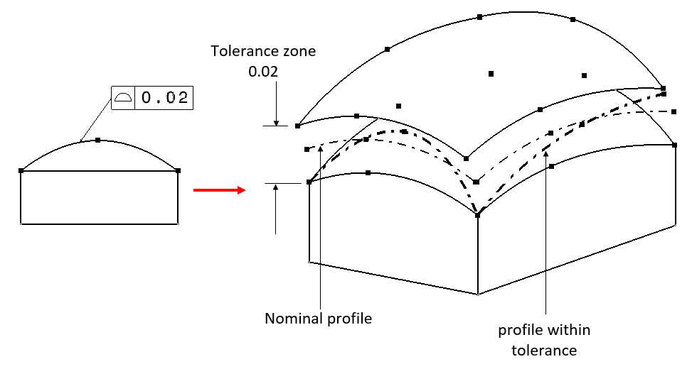
When used with datums, Profile of a Surface simultaneously controls the surface's size, form, orientation, and location. Let's return to our example drawing.
The callout for the slot is:⌢ | 0.1 | A | B | C
Interpretation:
⌢: Symbol for Profile of a Surface.0.1: The total width of the tolerance zone is 0.1mm.A | B | C: The DRF.
This callout states that the entire 3D surface of the slot must lie within a uniform boundary 0.1mm wide. This boundary is perfectly shaped, oriented, and located relative to datums A, B, and C, as defined by the basic dimensions on the drawing. This single callout ensures the slot has the right shape, is in the right place, and is properly oriented.
Conclusion
Today, we've added two of the most important GD&T tools to your arsenal. We moved beyond simply setting up a coordinate system to actively controlling features within it.
Key Takeaways:
- Position tolerance (
⌖) controls the location of features of size (holes, pins) within a cylindrical tolerance zone centered on a True Position. - Profile of a Surface tolerance (
⌢) controls the 3D form, orientation, and location of complex surfaces within a uniform boundary. - Material Condition Modifiers (MMC
Ⓜ) are essential for cost-effective design, as they provide bonus tolerance that allows for more positional variation when features are not at their most critical size. - Composite Position provides separate, tiered control over a pattern's location and the feature-to-feature relationship within it, a common requirement for automotive components.
In our next lesson, we will focus on the practical output of this knowledge: describing how a 2D drawing with GD&T callouts is created and how this design data is structured in a PLM system. You now understand the meaning behind the symbols; next, we will discuss the process of formalizing them on a drawing and managing that document within an engineering organization.
Can't find a good explanation? Sign up and we'll make it for you
Sign up