
Welcome to the final lesson for Day 1. So far, we have built a solid theoretical foundation for injection molding and GD&T. We've moved from the high-level manufacturing process down to the specifics of defining datums and interpreting Position and Profile tolerances. You now understand the meaning of these critical callouts.
This lesson bridges that theoretical knowledge to professional practice. We will now focus on the 'how': how do you, as a design engineer, formally document these requirements on a 2D drawing, and how is that critical data managed within an automotive organization's ecosystem?
By the end of this session, you will be able to describe the end-to-end process of creating a drawing with GD&T callouts and explain how that design data is structured and controlled in a Product Lifecycle Management (PLM) system. This is the capstone to our foundational day, preparing you to create and manage real design deliverables.
The Process of Creating a 2D Drawing
A 2D drawing is a contract. It is the definitive legal and technical document that communicates your design intent to manufacturing and quality inspection. Creating an effective drawing is not merely a software exercise; it requires a specific mindset. Before placing a single dimension, you must consider the part from three perspectives:
- Design: What are the functional requirements? Which features are critical for assembly and performance?
- Manufacturing: How will this part be made? How will it be fixtured? What processes can achieve the required tolerances?
- Inspection: How will the part be verified? How will the datums be simulated? Can the specified tolerances be measured with available equipment?
This holistic thinking is what separates a junior drafter from a senior design engineer. The following video provides an excellent overview of this mindset.
How to Make Drawing in GD&T Step By Step | Geometrical dimensioning and tolerance tutorial
The video "How to Make Drawing in GD&T Step By Step" from the Master Mechanical DESIGN channel provides a practical view on drawing creation.
Watch the introduction from the three perspectives. Pay attention to how the speaker links design choices to manufacturing and inspection limitations.
With this mindset, the creation of the drawing becomes a logical workflow. While you are using Onshape, the industry-standard logic, particularly in automotive, is rooted in systems like CATIA. The process typically takes place in the Drafting or, more commonly today, the Functional Tolerancing & Annotation (FTA) workbench. The FTA workbench is particularly powerful as it allows annotations to be created in the 3D space and then inherited by the 2D drawing, a practice known as Model-Based Definition (MBD).
The workflow is as follows:
- Create Views: Generate all necessary orthographic (front, top, side), isometric, and section/detail views from the 3D model to clearly and unambiguously show every feature.
- Establish Datums: Apply the datum feature symbols (e.g., A, B, C) to the appropriate features in the views, formalizing the Datum Reference Frame you designed based on the part's function.
- Apply Dimensions: Add all necessary dimensions. Critically, this includes using basic dimensions (theoretically exact dimensions shown in a box) to define the true position of features that will be controlled by GD&T.
- Apply GD&T Callouts: Place the Feature Control Frames (FCFs) for Position, Profile, and other geometric controls onto the drawing, linking them to the features they control and referencing the appropriate datums.
- Add Notes and Title Block Information: Complete the drawing with general notes (e.g., "UNLESS OTHERWISE SPECIFIED..."), surface finish requirements, material specifications, and a complete title block with part number, revision, and other metadata.
Let's watch a detailed walkthrough of this process. The example is a ball screw, which is a complex machined part, but the principles are universal and directly applicable to automotive components.
How to Make Drawing in GD&T Step By Step | Geometrical dimensioning and tolerance tutorial
Let's return to the same video to see this workflow in action.
First, watch the section on selecting datums. Note how the presenter simulates the manufacturing and inspection setup (V-blocks) in his mind to decide on the primary datums A and B. Next, watch the detailed segment on applying tolerances. Observe how he: Uses Total Runout to control a bearing seat with respect to the primary datum axis A-A'. Establishes a new datum C on that functional bearing seat. Uses Position tolerance to control a less-critical coupling step relative to the new datum C. Uses Perpendicularity to control the face of a shoulder relative to the datum C axis, ensuring the bearing will sit flat.
This step-by-step process of building up controls from the datums outward is the core of authoring a GD&T drawing.
How Design Data is Structured in a PLM System
A 2D drawing is not a standalone file living in a folder on a shared drive. In any modern automotive OEM or supplier, it is a managed object within a Product Lifecycle Management (PLM) system. A PLM system is the "single source of truth" that manages all data and processes related to a product, from initial concept through design, manufacturing, service, and disposal.
The PLM Data Model: Objects and Hierarchies
In a PLM system, every piece of information is an "object" with metadata and relationships to other objects. A part you design is not just a CAD file; it is a collection of linked objects.
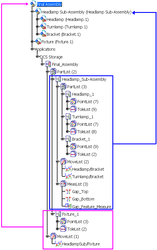
From this image, you can see the structure:
- Final Assembly: The top-level product (e.g., the vehicle).
- Sub-Assembly: An intermediate level, like the 'Headlamp Sub-Assembly'.
- Parts: Individual components like 'Headlamp', 'Turnlamp', and 'Bracket'.
- Associated Data: Each part or assembly object serves as a container. It links to the actual files and data, such as the 3D model (
.CATPart), the 2D drawing (.CATDrawing), and lists of tolerances (ToleList) or measurement points (PointList).
This structure is known as the Bill of Materials (BOM). The PLM system ensures that if the 'Bracket' part is updated, everyone using the 'Headlamp Sub-Assembly' is notified of the change.
A Data-Centric View of the Enterprise
Thinking like a lead engineer means seeing the bigger picture. The modern automotive enterprise is "data-centric." The data itself is the core asset. Applications like CATIA are simply windows used to view and edit that central data.
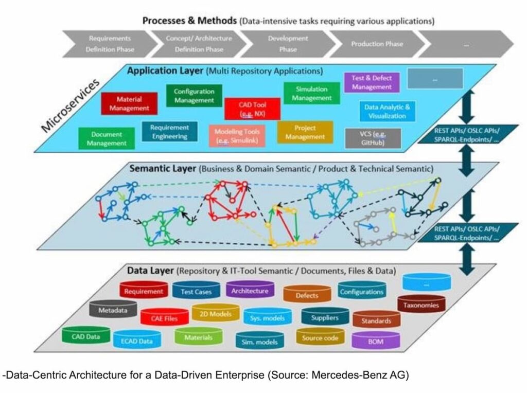
Let's dissect this industry-leading approach:
- Data Layer (Bottom): This is where the raw files reside—the
.CATPartand.CATDrawingyou create, along with requirements, simulation results, and BOM data. - Semantic Layer (Middle): This is the intelligence of the PLM system. It understands the relationships between the data. It knows that a specific drawing is the representation of a specific 3D model, which is made of a specific material and is used in multiple vehicle assemblies. This layer connects everything.
- Application Layer (Top): This is where you work. CATIA, your simulation software (e.g., Abaqus), and project management tools are all applications that interact with the data through the semantic layer.
Lifecycle Management and Revision Control
Finally, a PLM system manages the maturity of data through lifecycle states. A drawing you create starts as "In Work". When it's ready, you promote it to "In Review," where your lead engineer and manufacturing engineers approve it. Once approved, it is "Released." A released drawing is locked and can be used to order tooling and start production.
If a change is required, you cannot simply edit the released drawing. You must use a formal Engineering Change Order (ECO) process, which we will detail on Day 3. This process creates a new revision of the drawing (e.g., from Rev A to Rev B), and the PLM system tracks this entire history, ensuring full traceability.
Conclusion
In this lesson, we have connected GD&T theory to the practical realities of engineering documentation and data management. You now have a complete overview of the journey from a design idea to a fully controlled, documented, and released component.
Key Takeaways:
- Creating a 2D drawing is a methodical process (Views → Datums → Dimensions → GD&T) that demands you think from the perspective of design, manufacturing, and inspection.
- A Feature Control Frame is the syntax for specifying a geometric tolerance, containing the symbol, tolerance value, modifiers, and datum references.
- A PLM system is the single source of truth that organizes design data into a hierarchical BOM structure.
- In a PLM, parts, drawings, and other documents are version-controlled objects that mature through lifecycle states (e.g., In Work → Released).
This concludes Day 1. You have covered the fundamental theories of injection molding and the language of GD&T, culminating in how to document and manage that information professionally.
Tomorrow, we transition from theory to application. In our first lesson of Day 2, you will be tasked with designing an automotive grab handle, where you will need to justify material selection based on the properties we discussed earlier today.
Can't find a good explanation? Sign up and we'll make it for you
Sign up