
Welcome back. In our last lesson, we focused on the "what"—the core properties of key automotive thermoplastics. Today, we shift our focus to the "how"—specifically, how things can go wrong during manufacturing. As a design engineer, your ability to anticipate and prevent manufacturing defects is just as critical as your ability to select the right material.
This lesson addresses how to identify common injection molding defects. We will examine the visual signatures and root causes of four primary issues—weld lines, short shots, warpage, and sink marks—along with other common defects. You'll see how the material properties we discussed previously, like shrinkage and viscosity, directly contribute to these problems. This knowledge forms the bedrock of Design for Manufacturability (DFM).
A Visual Guide to Common Defects
Before we dissect each defect, let's start with a high-level visual overview. Defects are often subtle, but they have distinct characteristics. Familiarizing yourself with their appearance is the first step in diagnosis.
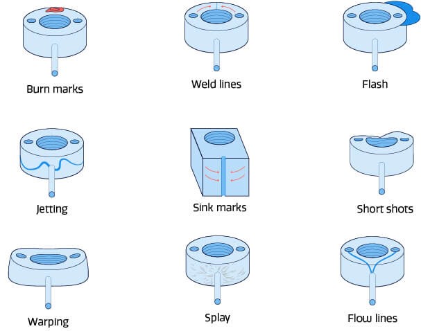
The key takeaway here is that defects are not random. They are predictable outcomes of interactions between the material, the mold design, the part geometry, and the process parameters.
Understanding the Root Causes
To effectively troubleshoot or prevent these issues, we need to understand their origins. We can group most common defects into two categories: those related to material flow and those related to cooling and shrinkage.
Let's watch a video that provides a concise explanation of several of these defects.
Common Plastic Injection Molding Defects
The video "Common Plastic Injection Molding Defects" from Sofeast gives a clear, visual introduction to the defects we will be focusing on.
Watch the following segments. For each one, focus on the visual representation of the defect and the primary cause explained by the narrator. Sink Marks Weld Lines Short Shots Warping
Now, let's break these down from an engineering perspective, linking them to design and process variables.
1. Flow-Related Defects
These occur during the injection phase when the molten plastic is filling the mold cavity.
-
Short Shot: The mold cavity fails to fill completely, resulting in an incomplete part.
- Root Causes:
- Part Design: Walls are too thin, or the flow path is too long and complex for the plastic to travel before it solidifies.
- Material: The material has high viscosity (flows poorly), like a high-GF PA6.
- Process/Tooling: Injection pressure or speed is too low, the mold or melt temperature is too low, or the mold has inadequate air vents, causing trapped air to block flow.
- Engineer's Role: Ensure wall thicknesses are appropriate for the material and part size. Simplify flow paths where possible.
- Root Causes:
-
Weld Lines (or Knit Lines): A visible line or seam where two or more fronts of molten plastic meet. This is a structurally weak area.
- Root Causes:
- Part Design: The flow path is forced to split around an obstacle (like a hole or a core pin) and then recombine. Multiple gates also create weld lines.
- Process/Tooling: The melt fronts cool too much before meeting, preventing them from fusing properly. This can be due to low melt/mold temperatures or slow injection speed.
- Engineer's Role: This is a classic DFM challenge. The goal is to position gates and obstacles so that weld lines form in non-critical, non-visible areas. Sometimes, changing the part geometry to alter the flow front is necessary.
- Root Causes:
-
Flash: A thin layer of excess plastic that escapes the mold cavity, typically along the parting line or ejector pin locations.
- Root Causes:
- Tooling: Worn or poorly fitting mold halves create gaps.
- Process: Injection pressure is too high, or the clamping force of the machine is insufficient to hold the mold shut.
- Engineer's Role: While primarily a tooling and process issue, a complex parting line dictated by the part design can increase the risk of flash.
- Root Causes:
2. Cooling & Shrinkage-Related Defects
These defects appear during or after the cooling phase as the part solidifies and shrinks. They are directly tied to the material's coefficient of thermal expansion and mold shrinkage properties you saw in the previous lesson.
-
Sink Marks: Small depressions or dimples on the surface of the part.
- Root Causes:
- Part Design: Non-uniform wall thickness. Sink marks almost always appear on a surface opposite a thick feature like a rib or a boss. The thick section cools much slower than the surrounding wall. As its core shrinks, it pulls the already solidified surface inward.
- Process: Insufficient packing pressure or time, preventing additional material from being forced in to compensate for shrinkage.
- Engineer's Role: This is a core DFM responsibility. The primary prevention is to follow the "golden rules" for part design, especially the rib-to-wall thickness ratio (which we will detail in the next lesson). Coring out thick sections is another key strategy.
- Root Causes:
-
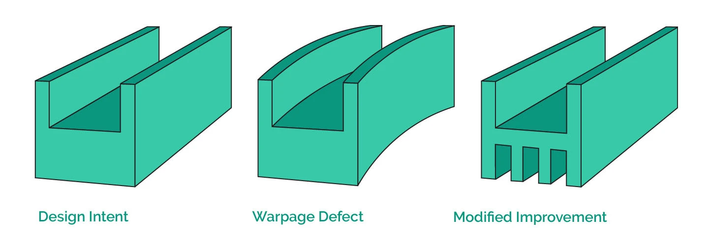
Warpage: The part distorts or bends from its intended shape after ejection.
- Root Causes:
- Part Design: Differential shrinkage is the ultimate cause. This is induced by non-uniform wall thicknesses, large flat and unsupported areas, or asymmetrical cooling.
- Material: High-shrinkage materials (like PP and PA) are more prone to warping than low-shrinkage materials (like ABS or PC/ABS). Adding fillers like glass or talc reduces shrinkage and, therefore, the tendency to warp.
- Process: Inconsistent mold temperature or insufficient cooling time.
- Engineer's Role: Design for uniform wall thickness. Add ribs and gussets to increase stiffness in flat areas. Select materials appropriate for the part's dimensional stability requirements.
- Root Causes:
Deeper Dive: Automotive Case Studies
Recognizing defects is one thing; solving them in a production environment is another. The following resource presents several real-world case studies from automotive manufacturing. It highlights the methodical approach required to diagnose a defect by examining the part, mold, and process.
Case Study of Injection Moulding Defects – Automotive Molding
This article from Gud Mould provides excellent, practical examples of defect analysis on automotive components.
Read the following three case studies. For each one, identify: The defect being discussed. The suspected root cause related to product structure/mold design. The suspected root cause related to the molding process. Start with "Apparent defects of fender – rubber fender trim molding." This case directly links non-uniform wall thickness to molding cycle issues. Next, read "Car dashboard tiger skin – car dashboard molding." "Tiger skin" is another name for flow lines. This highlights how process instability can create surface defects. Finally, read "Car central control panel weld line – car dashboard molding." This is a perfect example of how multiple melt fronts converge, trap gas, and create a visible, unacceptable defect on a cosmetic part.
These case studies reinforce a critical point: defects are rarely caused by a single factor. More often, they result from a complex interaction between part design, mold construction, material choice, and process settings. As a design engineer, your decisions in the CAD environment have direct and significant consequences on the factory floor.
Conclusion
In this lesson, we've cataloged the most common enemies of a high-quality injection molded part. By understanding how and why they occur, you are better equipped to design parts that are not only functional but also manufacturable.
Key Takeaways:
- Injection molding defects can be categorized by their root cause, primarily related to material flow (short shots, weld lines, flash) or cooling and shrinkage (sink marks, warpage).
- Part design is the first line of defense. Decisions regarding wall thickness, placement of features like ribs and holes, and overall part geometry are the primary drivers for many defects.
- Weld lines form where melt fronts meet and are weak points. Short shots occur when the mold doesn't fill. Both are heavily influenced by flow path length and wall thickness.
- Sink marks are caused by localized, thick sections. Warpage is caused by differential shrinkage across the part. Both are combated with uniform wall thickness and proper structural reinforcement.
- A design engineer must analyze defects by considering the interplay between part design, tooling, material properties, and process parameters.
In our next lesson, we will get very specific about prevention. Now that you can identify these defects and their causes, we will equip you with the "Golden Rules" of injection molding design. We'll cover quantifiable guidelines for draft angles, rib-to-wall ratios, and other core principles that you will apply directly in your CATIA design work to create robust, moldable parts from the start.
Can't find a good explanation? Sign up and we'll make it for you
Sign up