
In our previous lessons, we thoroughly analyzed the ECO for the door trim panel. We evaluated the DFM impact on the injection mold tooling and, most recently, the DFA impact on the assembly process. Our DFA analysis revealed that the relocated screw boss created a critical access issue for assembly tooling. To solve this, we proposed a design change: replacing the screw boss with an integrated snap-fit feature.
While this solution resolves the assembly access problem, it introduces new design complexities and potential failure modes, such as the risk of the snap-fit fracturing. Today, we will address this formally. Our objective is to update the Design Failure Mode and Effects Analysis (DFMEA) to reflect the design changes introduced by the ECO.
A DFMEA is not a static document that you create once and file away. It is a living document that must evolve with the design. An Engineering Change Order is a primary trigger for an FMEA update. As the Bosch FMEA guidelines state, an FMEA must be updated for any "changed requirements or modifications to products or processes." We've modified the product; now we must update our risk analysis accordingly.
The Logic of FMEA: A Refresher
Before we dive into the update, let's refresh our understanding of the DFMEA's structure and its core logic. The analysis is built on a clear chain of cause and effect.
Guide To Failure Mode & Effects Analysis (FMEA) Excellence: Design & Process FMEA
This video from PMC offers a concise review of the DFMEA template and the philosophy behind it. We'll use this to re-establish the framework we'll be working within.
Please focus on these two segments: DFMEA Template: Follow the logical flow from Function -> Potential Failure Mode -> Potential Effect -> Potential Cause -> Current Controls. This is the "failure chain" we will be modifying. Key Points: This section is crucial for our task today. Note the rules for reducing the risk ratings. For instance, the video states that Severity (S) can only be reduced by a design change, and Occurrence (O) can only be reduced by removing or controlling a cause through a design change. Our ECO is precisely this kind of design change.
The video reinforces that the DFMEA is a structured, systematic tool. When a design changes, we must systematically trace the impact of that change along the failure chain.
The FMEA Update Process
The modern, harmonized AIAG & VDA FMEA standard outlines a 7-step process. When updating an FMEA due to an ECO, you are essentially revisiting several of these steps for the affected parts of the design.
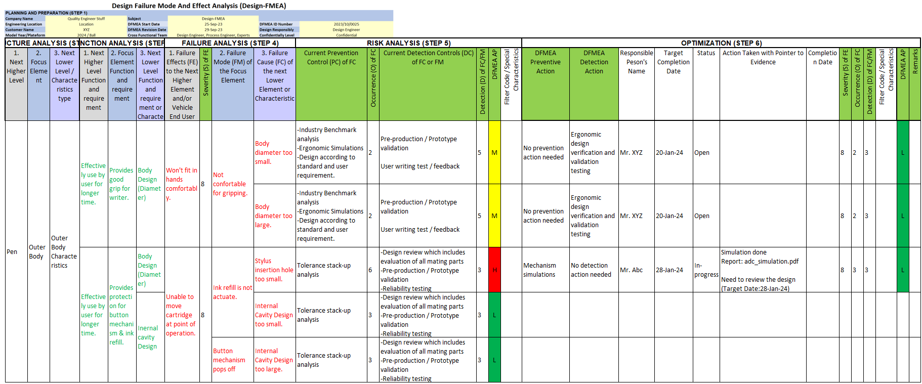
For our door trim ECO, we will focus on three key activities:
- Re-analyzing existing failure modes that are affected by the change.
- Identifying and analyzing new failure modes introduced by the new design features.
- Optimizing the design by defining new actions to mitigate any new or increased risks.
Let's walk through this process using our grab handle example.
Step 1: Analyze the Impact on Existing Failure Chains
Our original design used a screw to attach the grab handle. A potential failure chain in the original DFMEA might have looked something like this:
- Function: Retain grab handle to door trim with specified clamp load.
- Failure Mode: Grab handle becomes loose, creating a rattle (BSR issue).
- Failure Effect: Annoying noise, poor perceived quality. (Severity S = 4)
- Failure Cause: Screw loosens over time due to road vibration.
- Prevention Control: Torque specification called out on 2D drawing.
- Detection Control: 100% torque audit at the assembly plant's end-of-line (EOL) station.
The ECO, by replacing the screw with a snap-fit, completely eliminates the "Screw loosens" cause. In the updated DFMEA document, this entire line item would be marked as superseded by the ECO number. This is critical for traceability. You don't simply delete old analysis; you archive it and show what replaced it.
Step 2: Identify and Analyze New Failure Chains
The snap-fit is a new feature, so it brings new potential failures. This requires adding new lines to our DFMEA. We start by defining the function and then brainstorming how it could fail.
The core logic follows the "Failure Chain" concept.
AIAG & VDA Design Failure Mode and Effect Analysis - pretesh biswas
This document on the harmonized AIAG & VDA FMEA standard provides an excellent visualization of the "Failure Chain."
Focus on "Step 4 Failure Analysis," particularly the diagrams under sections 4.3 The Failure Chain and 4.7 Failure Analysis. These illustrations clearly show the relationship between a Failure Effect (the consequence), the Failure Mode (how the item fails), and the Failure Cause (why it fails).
Let's build a new failure chain for our snap-fit:
- Focus Element: Grab Handle
- Function: Retain grab handle to door trim panel via snap-fit.
- Potential Failure Mode: Snap-fit hook fractures during assembly.
- Potential Effect of Failure: Grab handle not secured; may be loose or fall off. Customer may perceive it as broken. This directly impacts the primary function.
- Potential Cause of Failure: We must brainstorm all credible causes.
- Design-related: Stress concentration in hook geometry due to insufficient fillet radius.
- Material-related: Material is too brittle due to incorrect grade of Polypropylene (PP) specified or improper processing during molding.
- Assembly-related: Assembly operator over-deflects the hook beyond its elastic limit.
For each cause, we must now define our current controls and evaluate the risk.
Step 3: Risk Analysis and Prioritization
This is where we assign ratings for Severity (S), Occurrence (O), and Detection (D) to quantify the risk. We'll use the standard 1-10 automotive rating scales.
Booklet No. 14 Failure Mode and Effects Analysis FMEA
This appendix from the Bosch FMEA handbook provides industry-standard rating tables for Severity, Occurrence, and Detection.
Review the tables in "Appendix 1" (pages 41-43). We will use these as our guide to assign ratings.
Let's apply these ratings to our new failure mode: Snap-fit hook fractures.
- Severity (S): The effect is "Grab handle not secured." Looking at the table, this constitutes a "Severe failure" where the "Functional capability of vehicle severely restricted." Let's assign S = 7. (Note: Severity is associated with the effect, and it's very difficult to change without a fundamental concept change).
Now, let's analyze the risk for one of the causes: "Stress concentration in hook geometry."
-
Occurrence (O): How likely is this cause to occur? Our prevention controls are "Following internal design guidelines for snap-fits" and "FEA analysis." Since this is a new application of the feature, even with experience, there's some risk. From the table, this fits a "Moderate" rating. Let's assign O = 5.
-
Detection (D): How well can we detect this failure before it reaches the customer? Our detection control is "Design Verification (DV) testing, including a snap-fit durability test." This is a proven test method, but it's often done on a sample of parts, not 100%. The table suggests a "Moderate" probability of detection. Let's assign D = 6.
Prioritizing with Action Priority (AP)
Historically, teams multiplied these numbers to get a Risk Priority Number (RPN). However, RPN has limitations (e.g., a high-severity/low-occurrence issue can have the same RPN as a low-severity/high-occurrence one). The modern AIAG & VDA standard uses Action Priority (AP).
AIAG & VDA Design Failure Mode and Effect Analysis - pretesh biswas
This document also contains the new Action Priority (AP) tables.
Read section 5.10 Action Priority (AP). Notice how the table prioritizes actions based on combinations of S, O, and D, giving the most weight to Severity.
Using the AP table for our ratings (S=7, O=5, D=6), we find the recommended priority is Medium (M). This tells the team that action should be taken to reduce this risk.
Step 4: Optimization and Documentation
An "M" or "H" Action Priority rating is a call to action. The final step is to define what we will do to improve the design and lower the risk.
For our "Stress concentration" cause:
- Recommended Action: "Refine snap-hook fillet radius based on FEA results to reduce peak stress by 15%. Document final geometry in a new Design Best Practice."
- Responsibility: J. Doe (Lead Engineer)
- Target Completion Date: 10/28/2023
- Status: Open
After this action is completed and verified (e.g., with a successful re-test), the team re-evaluates the risk. The FEA and new Best Practice are stronger Prevention Controls, so the Occurrence rating might drop from O=5 to O=3.
- New Ratings: S=7, O=3, D=6
- New Action Priority: Looking at the AP table, this new combination now yields a priority of Low (L).
The risk has been successfully mitigated to an acceptable level. This entire process—the original ratings, the action taken, and the new ratings—is documented in the DFMEA. This creates a traceable record of your engineering decisions.
Conclusion
You've now seen how to translate a design change from an ECO into a formal risk assessment update. The DFMEA is your primary tool for ensuring that in fixing one problem, you haven't introduced another, more serious one.
Key Takeaways:
- A DFMEA is a living document that must be updated whenever a design is modified.
- The update process involves both modifying existing failure chains and adding new ones to reflect the changes.
- The Failure Chain logic (Effect -> Mode -> Cause) is the foundation for a thorough analysis.
- Modern risk prioritization uses the Action Priority (AP) table, which gives greater weight to severity than the old RPN method.
- The goal of the DFMEA update is Optimization: to define, execute, and document specific actions that reduce risk to an acceptable level.
In our final lesson for this project, we will take the outputs from our analysis—the new snap-fit geometry and any associated notes like material specifications—and learn how to produce updated 2D drawings with revised GD&T and document the changes in a PLM-style format.
Can't find a good explanation? Sign up and we'll make it for you
Sign up