
Welcome to the next lesson in our intensive design course. In our previous session, we dissected the Engineering Change Order (ECO) from a manufacturing perspective, evaluating its impact on the injection mold tooling. We distinguished between "steel safe" and "steel unsafe" changes and saw how a design modification triggers a full DFM review.
Having confirmed the part can be manufactured post-change, we must now ensure it can be assembled. Today, our objective is to analyze the Design for Assembly (DFA) impact of the ECO on the assembly sequence and joining methods. We will investigate how the changes affect the efficiency, cost, and quality of putting the final product together on the assembly line.
Fundamentals of Design for Assembly (DFA)
Design for Assembly is a core methodology within the broader DFMA (Design for Manufacturing and Assembly) framework. While DFM focuses on optimizing a single part for its production process, DFA focuses on optimizing the product's overall structure for ease of assembly.
To begin, let's establish a clear understanding of DFA principles and their importance in the product development cycle.
DFM Lecture 3: DFMA Principles
This lecture from MVCC's Engineering Technology program provides a solid academic foundation for DFMA.
Please watch the following segments to grasp the core ideas: DFM vs. DFA: Pay attention to the definitions and the goal of bringing future assembly considerations into the early design stages. Cost of Change: This graph is one of the most important concepts in engineering management. Note how freedom to make changes decreases while the cost of those changes skyrockets as you approach production. This is why we perform DFA analysis early. DFA as a Prerequisite: Understand the logic of why DFA (simplifying the product structure) must come before DFM (optimizing individual parts). General DFA Principles: This is a critical checklist. Absorb these rules, as we will be applying them directly.
The video highlighted several key principles, but the overarching goal is simplification. Every part in an assembly adds cost—not just its own material and manufacturing cost, but also costs related to procurement, inventory, quality control, and the assembly time and labor required to install it.
A Systematic Method for Part-Count Reduction
The most effective DFA strategy is to eliminate parts. A common method for achieving this is to systematically question the existence of every component in an assembly.
WHAT IS DFMA/DFA (DESIGN FOR ASSEMBLY)
The channel ENGINEERING SPIRIT offers a very concise and practical method for analyzing parts.
Watch the segment from the three elimination questions through the redesign. This section provides a simple yet powerful framework for identifying "suspect" components that are candidates for elimination or integration.
The three questions you just saw are a cornerstone of DFA analysis:
- Does the part need to move relative to other parts during operation?
- Does the part need to be made of a different material for fundamental reasons (e.g., conductivity, insulation, wear resistance)?
- Does the part need to be separate to allow for assembly or disassembly of other essential components?
If the answer to all three questions is "no," the part is a prime candidate to be integrated into another component.
Case Study: DFA in Automotive Instrument Panel Design
Let's examine a real-world automotive example that demonstrates the profound impact of applying these DFA principles. A truck instrument panel (IP) was redesigned to reduce cost and complexity.
Evaluation of Instrument Panel Designs for Cost of Manufacture and ...
This technical paper by Dr. Peter Dewhurst, a pioneer in DFMA, details the redesign of a truck IP. It provides a masterclass in applying DFA to a complex automotive assembly.
Focus on these key areas: "PROPOSED DESIGN": Read how the original design, a complex assembly of moldings and steel brackets, was replaced by two primary structural injection moldings. Note the use of integrated features like snap elements, air ducts, and wire harness supports. "DFMA COMPARISON...": This section quantifies the benefits. Pay close attention to Figure 3, which graphically compares the number of assembly steps, fasteners, and other items between the original and proposed designs.
The results from this case study are dramatic:
- Assembly steps reduced from 482 to 121.
- Separate fasteners reduced from 123 to 23.
- Assembly cost per IP reduced from $44.12 to $8.52.
This was achieved by replacing a multitude of brackets, ducts, and fasteners with two intelligently designed, multi-functional plastic moldings. Joining methods shifted from screws and rivets to ultrasonic welding and integrated snap-fits. This is the level of impact a thorough DFA analysis can have.
Analyzing the DFA Impact of Our Door Trim ECO
Now, let's apply this thinking to our door trim panel. The ECO required relocating a screw boss for the grab handle (Change A). In the previous lesson, we analyzed the tooling impact ("steel unsafe"). Now, we'll analyze the assembly impact.
Imagine the following scenario:
The relocated screw boss is now positioned directly behind a stamped steel bracket that is part of the window regulator assembly. While there is no hard interference (the parts don't clash), the new location provides only 25mm of clearance between the head of the screw and the bracket.
This scenario immediately raises red flags for assembly. We can frame our analysis using a structured approach.
1. Impact on Assembly Sequence
The assembly sequence for this area of the door is:
- Install window regulator assembly to the inner door sheet metal.
- Connect wiring harnesses.
- Install the main door trim panel (with the grab handle pre-attached) to the door.
With the new boss location, Step 3 is now problematic. The 25mm clearance is insufficient for the standard pneumatic screwdriver used on the assembly line, and it also restricts the operator's line of sight. This violates a key DFA principle: ensure access for tooling and personnel. This will increase assembly time, introduce ergonomic strain, and raise the risk of cross-threading or incorrectly torquing the screw, leading to quality issues.
2. Impact on Joining Method
The joining method itself—a screw—is now the source of the problem. This leads to a crucial question I have for you:
"The original design used a screw. Given the new spatial constraints from the ECO, is a screw still the most appropriate joining method, or does this change present an opportunity to improve the design?"
This is where a good design engineer adds value. Instead of just flagging a problem, you should propose solutions.
Exercise: Proposing and Evaluating Solutions
Based on our analysis, the current design is not viable for mass production. Address the following tasks.
Task 1: Propose a Process-Based Solution
Describe a solution that resolves the assembly issue by changing the assembly sequence. What are the pros and cons of this approach?
Solution
A process-based solution would be to invert the assembly sequence. Instead of pre-attaching the grab handle, the main door trim would be installed first, and then the grab handle would be attached to the trim panel.
- Pros: This might provide better access to the problematic screw, as the operator could potentially maneuver the handle to align the boss before fastening.
- Cons: This is a significant deviation from a standard "top-down" assembly. It increases complexity on the main assembly line, potentially requiring a new station or specialized tooling. Handling a loose grab handle inside the vehicle cabin increases the risk of dropping it or scratching other Class-A surfaces. This solution likely adds more time and risk than it saves.
Task 2: Propose a Design-Based Solution
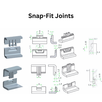
Propose a solution that resolves the issue by changing the joining method. Reference the case study and the image below. Describe the DFM/tooling implications of your proposed change.
Solution
A design-based solution is to replace the screw boss with an integrated snap-fit feature. The grab handle and the door trim panel would be redesigned to incorporate mating cantilever snap hooks and receptacles, similar to the examples in the image.
This directly follows the DFA principle of designing parts with self-fastening features and reducing part count (by eliminating the screw).
Implications (connecting to our previous lesson):
- DFM/Tooling Impact:
- This change would require significant "steel unsafe" modifications to both the grab handle mold and the door trim mold to create the new snap features. The cavities would need to be welded and re-machined.
- The snap features themselves are undercuts, which would necessitate adding sliders or lifters to the molds. This would substantially increase tool cost and complexity.
- A full Mold Flow Analysis would be required to ensure these new, complex features fill properly without defects.
- Trade-off: While the tooling cost and complexity are much higher, the long-term benefit is a massive reduction in assembly time and complexity for every vehicle produced. For high-volume automotive production, this trade-off is often justified.
Conclusion
Today we've seen that an ECO's impact extends far beyond the part itself and into the heart of the assembly plant. A design that is manufacturable but not assemblable is a failure. By applying DFA principles, we can critically evaluate not only the risks of a design change but also the opportunities for improvement.
Key Takeaways:
- Design for Assembly (DFA) is a systematic process for simplifying product structure to reduce assembly cost, time, and errors.
- The "three elimination questions" provide a rigorous method for identifying and removing non-essential parts.
- An ECO must be evaluated for its impact on assembly sequence, focusing on access and ergonomics, and on joining methods, seeking opportunities to replace fasteners with integrated features like snap-fits.
- Improving DFA often involves a trade-off: increased upfront tooling investment (e.g., for sliders to create snap-fits) can yield significant savings in assembly cost over the life of the product.
In our previous lesson, we identified manufacturing risks, and today we've identified assembly risks. In our next lesson, we will formalize this analysis by learning how to update the DFMEA to reflect the design changes introduced by the ECO.
Can't find a good explanation? Sign up and we'll make it for you
Sign up