
Welcome to the final session of our deep dive into injection molding. Over the past two days, we've analyzed an Engineering Change Order (ECO), evaluated its manufacturing and assembly impacts, and, in our last lesson, updated the DFMEA to account for the risks of our new snap-fit design.
Today, we will complete the engineering cycle for this change. Our objective is to translate our design solution into the official engineering documents that drive production and ensure quality. Specifically, you will learn how to produce updated 2D drawings with revised GD&T and document the changes in a PLM-style format. This final step is what formally releases a design to the manufacturing world and creates a permanent, traceable record of your work.
Part 1: The Role of the 2D Drawing
Even in an era of Model-Based Definition (MBD), the 2D drawing remains the definitive legal document in many automotive supply chains. It is the contract between the design team, the toolmaker, the molder, and the quality inspector. Every critical requirement must be captured on it.
When an ECO is processed, the drawing must be updated methodically. Let's review the standard components of an engineering drawing.
Understanding Engineering Drawings
This video from The Efficient Engineer, titled "Understanding Engineering Drawings," provides an excellent overview of the structure and purpose of technical drawings.
Please watch the following sections: Drawing Structure: Pay attention to the title block and the revision history table. These are the areas that record the change. Primary Views: A quick refresher on how orthographic views (front, top, side) are created and arranged. Supplementary Views: Focus on detail views and sectional views. For our new snap-fit, these are essential for clearly communicating the complex geometry that isn't visible in the main views.
For our grab handle, the ECO necessitates these drawing updates:
- Geometric Updates: The views must be updated to show the new snap-fit feature, removing the old screw boss. We would likely add a section view through the snap-fit to show its cross-section and a detail view to magnify the hook geometry for clear dimensioning.
- Dimension & Tolerance Updates: All dimensions related to the screw boss are removed. New GD&T callouts are added to control the snap-fit's location and form.
- Revision Block Update: The revision block is updated to log the change, referencing the ECO number.
Part 2: Applying GD&T to the New Design
Our DFMEA from the last lesson highlighted the criticality of the snap-fit. If it fractures, is misaligned, or has poor form, the part fails. GD&T is the language we use to precisely control these characteristics.
Based on our Day 1 introduction, you'll recall that we build a Datum Reference Frame (DRF) to serve as the coordinate system for our part. For a complex part like this, we often use datum targets.

Assuming we have a similar A-B-C datum scheme for our grab handle, we can now control our new snap-fit feature relative to it. We need to control two key aspects: its location and its form.
Controlling Location with Position Tolerance
The snap-fit must be in the correct location to engage with its mating slot on the door panel. The Position tolerance is the ideal tool for this.
Let's watch a segment of "Understanding GD&T" that explains the fundamentals of the Position tolerance.
Focus on the explanation of Position tolerance. Note the concepts of true position, basic dimensions (the boxed dimensions), and the cylindrical tolerance zone.
To apply this, we would use basic dimensions on the drawing to define the theoretically perfect location of the snap feature's centerline from Datums A, B, and C. The feature control frame then defines how much the actual centerline of the manufactured feature is allowed to deviate from this "true position."
True Position – Position Tolerance | GD&T Basics
The article from GD&T Basics provides a more detailed breakdown.
Read the sections Definition and Position Tolerance Zone. Focus on how Position is applied to a "feature of size" (our snap-fit qualifies) and how it's located by the Datum Reference Frame using basic dimensions.
For our snap-fit, the feature control frame might look like this:
Let's break this down:
- POS: Controls the position.
- Ø0.5: The tolerance zone is a cylinder with a diameter of 0.5mm within which the axis of the snap-fit must lie.
- (M): The Maximum Material Condition (MMC) modifier. This is a crucial addition for assembly features. It means that if the snap-fit is produced at a size that provides more clearance (e.g., slightly thinner), it gets a "bonus tolerance" on its position. This reflects the functional reality: more clearance means location is less critical.
- | A | B | C |: The tolerance zone is located and oriented relative to our primary, secondary, and tertiary datums.
Controlling Form with Profile of a Surface
The snap-fit hook has a complex, curved shape that can't be defined by simple linear dimensions. To ensure it has the correct contour to function properly (flex without breaking, engage securely), we use the Profile of a Surface tolerance.
This article from GD&T Basics explains the most versatile symbol in the GD&T toolbox.
Read the Description, When Used, and Example sections. Note that Profile creates a 3D tolerance boundary around a surface, ensuring it conforms to its intended shape.
Profile of a Surface creates a uniform tolerance boundary on either side of the feature's "true profile" as defined by the CAD model. For the snap-fit hook, the feature control frame could be:
This callout states that all points on the indicated surface of the hook must lie within a 0.8mm wide tolerance zone (0.4mm on each side of the nominal CAD surface). This zone is perfectly located and oriented with respect to our datums A, B, and C. This single callout controls size, location, orientation, and form simultaneously for that complex surface.
Part 3: Documenting the Change in a PLM System
You've updated the model and the drawing. The final step is to formalize the change in the Product Lifecycle Management (PLM) system. This is done by completing an Engineering Change Notice (ECN), which is the document that authorizes the change.
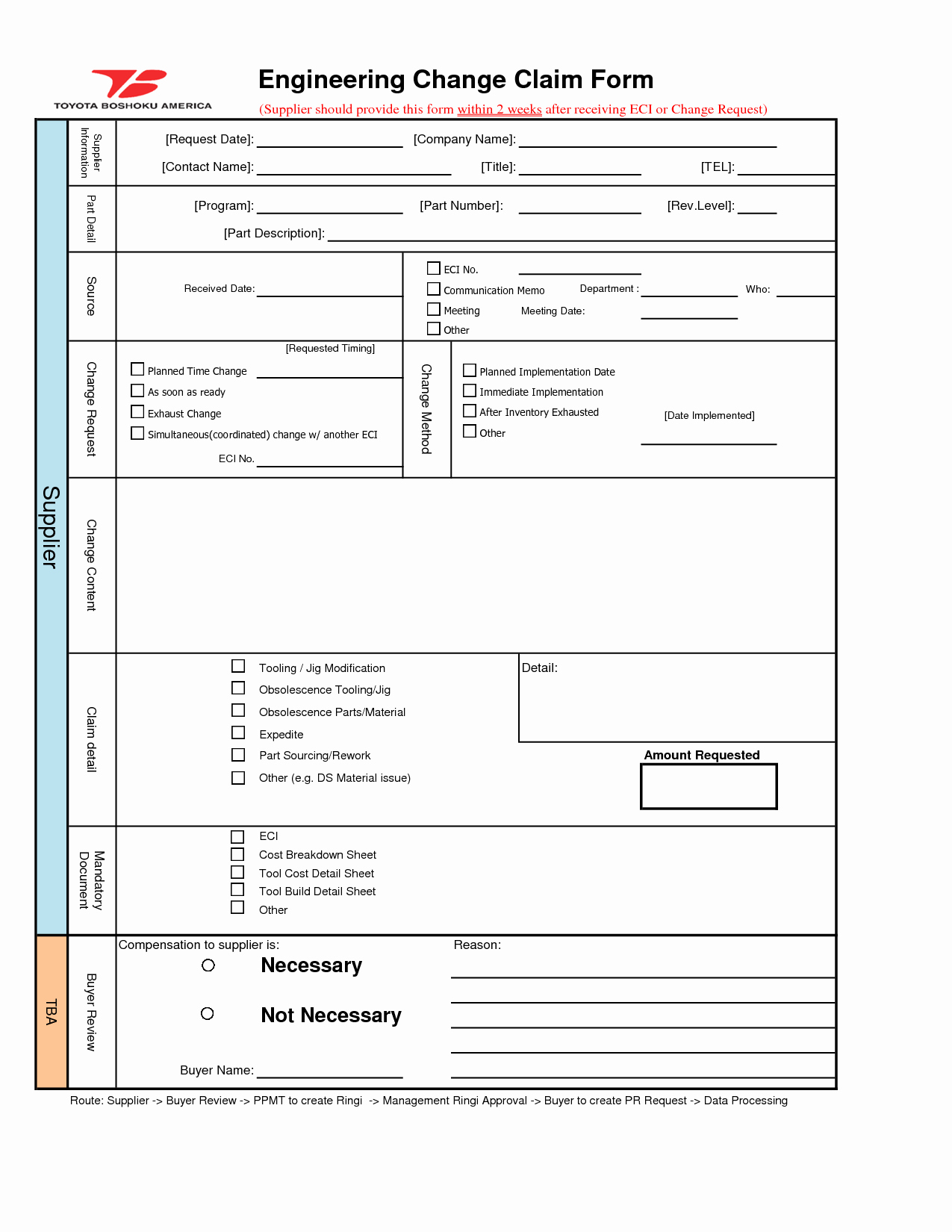
A typical ECN contains the following critical information:
- Part Identification: Part Number, Name, and the new revision level (e.g., Revision A becomes Revision B).
- Change Description: A clear, concise explanation of the change. For our case: "Replaced M4 screw boss with an integrated cantilever snap-fit feature."
- Reason for Change: Justification. For our case: "To resolve assembly tooling access issue identified during DFA review. Original design was not manufacturable at production volumes."
- Affected Documents: A list of all documents that were changed, including their new revision levels (e.g., 3D Model: Rev B, 2D Drawing: Rev B, DFMEA: Rev C).
- Disposition of Existing Inventory: A critical business decision on what to do with parts made to the old revision. Options are typically:
- Scrap: Destroy all old parts. (Used for safety or critical function changes).
- Use As Is: Continue using old parts until inventory is depleted. (Used for minor or cost-reduction changes).
- Rework: Modify old parts to meet the new configuration.
- Effectivity: Specifies when the change becomes active. This can be an immediate change, a specific date, or tied to a vehicle serial number.
This ECN, once approved by all stakeholders (engineering, manufacturing, quality, purchasing), is digitally attached to the part number in the PLM system. The revision block on your 2D drawing is then updated with a summary and a reference to this ECN number, creating a closed loop of documentation.
Example revision block entry:
| REV | DESCRIPTION | DATE | ECN # |
|---|---|---|---|
| B | REPLACED SCREW BOSS WITH SNAP-FIT | 2023-10-26 | ECN-12345 |
Your Task: Finalizing the Documentation
Let's put this into practice. Based on our work, answer the following questions.
- Drawing Views: What new supplementary view (Section, Detail, etc.) would be most critical to add to the drawing to clearly define the snap-fit geometry, and why?
- GD&T Application: You need to control the position of the new snap-fit. Write out the feature control frame you would use. Make a reasonable assumption for the tolerance value. Why did you choose the modifiers (or lack thereof) that you did?
- PLM Documentation: Fill out the key fields for a simplified ECN for this change:
- Part Number / New Revision: 82155-ABC / Rev B
- Change Description: [Your description]
- Reason for Change: [Your justification]
- Disposition of Existing Inventory: [Choose one and briefly justify your choice]
Take some time to formulate your answers. This exercise simulates the final hand-off of an engineering change.
Conclusion and Next Steps
Today you've completed the loop on the engineering change process. You have translated a design solution into a set of robust, unambiguous documents that will guide manufacturing and ensure quality for the life of the part.
Key Takeaways:
- Updated 2D drawings are the contractual basis for production, requiring new views and revised GD&T to define changes.
- Position tolerance is used to control the location of features of size, while Profile of a Surface is used to control the form of complex shapes.
- The Engineering Change Notice (ECN) is the formal PLM document that describes the what, why, and how of a change, ensuring clear communication and traceability.
This concludes our 3-day project on injection molding. You've gone from fundamental theory to executing a complex, real-world ECO on an interior trim component.
Tomorrow, we pivot to a new domain. Day 4 will begin our study of Sheet Metal Stamping. We will start with a deep dive into the stamping process, materials, common defects, and the foundational design rules for sheet metal parts. We will also introduce a new process framework: Advanced Product Quality Planning (APQP).
Can't find a good explanation? Sign up and we'll make it for you
Sign up