
Welcome to our fourth session on Day 3. In our last lesson, we focused on the meticulous process of evaluating the Class-A surface quality requirements for our interior trim panel. You learned how to use CATIA's GSD tools to quantify smoothness and ensure any design change meets automotive standards for aesthetics and reflection.
Today, we move from the digital world of surfaces to the physical reality of manufacturing. An Engineering Change Order (ECO) is not just a CAD update; it's an instruction to alter expensive, hardened steel tooling. Our goal in this lesson is to evaluate the DFM and tooling impact of the ECO on the injection-molded assembly. We will analyze how a seemingly simple design change can have significant consequences for the mold's cost, lead time, and the quality of the final part.
The Physics of Tooling Changes: "Steel Safe" vs. "Steel Unsafe"
Before we analyze any specific design features, we must understand the single most important principle governing mold modifications. Every change falls into one of two categories, and the difference between them dictates cost, timing, and risk.
The Chaos of Change: How to Manage Engineering Change Orders ...
This article from Sureton, a manufacturing supplier, provides a direct, no-nonsense explanation of the core challenge in modifying injection molds. It's written from the perspective of the people who will actually have to perform the work.
Read the section titled "1. The Physics of Modification: 'Steel Safe' vs. 'Steel Unsafe'". Pay close attention to the definitions and the explanation of why one is "easy" and the other is "hard".
As you've just read, the concept is straightforward but has profound implications:
- Steel Safe: A change that adds material to your part. To achieve this, we simply machine more steel away from the mold cavity. This is relatively fast, low-cost, and low-risk. Examples include making a boss taller, making a wall thicker, or reducing the diameter of a hole.
- Steel Unsafe: A change that removes material from your part. This is the difficult scenario. To achieve this, we must add steel back into the mold cavity. This typically involves precision welding, followed by re-machining (CNC or EDM) and polishing. This process is expensive, time-consuming, and introduces risks like heat-affected zones in the tool steel, which can compromise tool life and part quality. Examples include making a wall thinner, increasing the diameter of a hole, or relocating a feature.
When an ECO is issued, the very first question a tooling engineer will ask is: "Is it steel safe?" The answer to this question frames the entire impact assessment.
DFM Review: The Ripple Effect of a Design Change
An ECO triggers a comprehensive Design for Manufacturability (DFM) review. A change is rarely isolated; it creates a ripple effect across the part's geometry, potentially violating established DFM rules that were met by the original design. Let's review the critical DFM elements that must be re-evaluated.
Design Tips for Injection Moulding
This video from Xometry provides a concise overview of the most important DFM rules for injection molding. It serves as an excellent refresher on the fundamental principles.
Watch the following key segments to reinforce the core rules: Wall Thickness: Understand the impact of non-uniform walls. Draft Angles: Note the requirements for textured surfaces. Ribs and Gussets: Focus on the rule for rib thickness relative to the main wall. Undercuts: Grasp how these features add complexity and cost to the mold. Bosses: Observe the rules for diameter and attachment. Gate Location: Appreciate why the entry point of the plastic is so critical.
Now, let's explore these DFM elements specifically in the context of an ECO. When you modify a design, you must analyze its impact on:
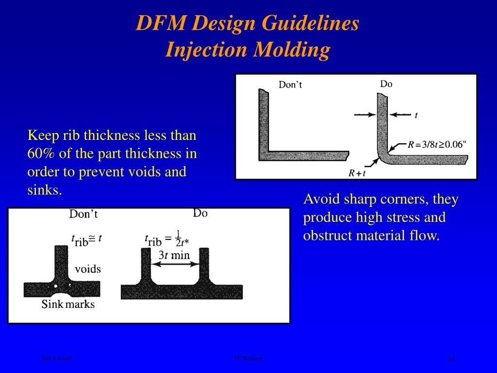
1. Wall Thickness, Sink, and Warpage
A change to a surface contour or feature location can easily create an unintentionally thick section.
- Impact: Thicker sections cool much slower than the surrounding nominal wall. This differential shrinkage causes two main defects:
- Sink Marks: The surface of the part is pulled inward, creating a visible depression on the Class-A surface.
- Warpage: The entire part distorts as it cools, failing to hold its intended shape.
- Evaluation: Use your CAD system's wall thickness analysis tool to find any new thick sections created by the ECO. The rule of thumb for ribs is crucial here.
2. Material Flow, Weld Lines, and Air Traps
Changing the geometry alters the path that molten plastic takes as it fills the mold.
- Impact: This can move the location of weld lines (where two flow fronts meet) to a cosmetically sensitive or high-stress area. It can also create air traps, where air cannot escape the cavity, leading to burn marks or incomplete parts (short shots).
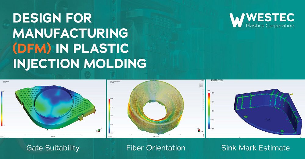
- Evaluation: This is where Mold Flow Analysis (MFA) is indispensable. You would request an updated MFA from a CAE analyst to simulate the plastic fill with the new geometry. The simulation predicts fill time, pressure, weld line locations, and potential air traps, allowing you to identify problems before the tool is modified.
3. Tooling Actions (Lifters and Sliders)
Sometimes, a design change can inadvertently create an undercut—a feature that prevents the part from being ejected straight out of the mold.
- Impact: Resolving an undercut requires adding a mechanical action to the mold, such as a slider (moves sideways) or a lifter (moves at an angle). These mechanisms can increase tooling cost by 50% or more, add complexity, increase cycle time, and introduce new failure points.
- Evaluation: Carefully inspect the new geometry in the context of the mold's line of draw (the direction of opening/closing). Does any feature now "hook" into the core or cavity steel? Your CAD draft analysis tool can help identify these areas.
Visualizing the Tooling Impact: A Real-World Modification
Theory is important, but seeing the process helps solidify the concepts. Let's watch a video of a simple mold modification to understand the practical steps involved.
The channel Dragonfly Engineering documents a real modification to an aluminum prototype mold. This gives you a clear view of the process from CAM to CNC to molding.
Watch these two key segments: CAM Programming: Observe how the engineer defines the toolpaths in the software to machine a new feature into the existing mold. This is the digital-to-physical translation step. Machining and Fitting: See the CNC mill cutting the aluminum mold. Note the iterative process of machining, test-fitting the new pin, and re-machining to get the perfect fit. This demonstrates that even "simple" changes require precision and time.
This video clearly shows that a tooling change isn't just a click of a button. It involves programming, machine setup, precise machining, and skilled fitting. Even for a "steel safe" modification like the one shown (removing more steel to add a feature), it's a multi-step process. An "unsafe" change involving welding would be significantly more complex.
Application: Evaluating Our Door Trim ECO
Let's apply these principles to our ongoing scenario. The ECO you've been working with requires two key changes to the door trim panel:
- Change A: Relocating a screw boss for the grab handle mount by 10mm.
- Change B: Modifying the Class-A surface on the armrest to create a slightly deeper, more pronounced feature line, which results in the local wall thickness increasing from 2.5mm to 4.5mm.
Based on what you've learned, consider the following questions.
Question 1: The relocation of the screw boss requires removing the boss from its original position and adding it to the new one. Is this change "Steel Safe" or "Steel Unsafe"? Describe the probable high-level steps the toolmaker would need to take to modify the mold.
Answer
This is a classic **"Steel Unsafe"** change.- Removing the old boss: This requires adding material back into the mold where the old boss feature was. The toolmaker would likely weld steel into the depression that formed the old boss, then machine and polish it back to match the surrounding surface of the cavity.
- Adding the new boss: This requires removing steel from the mold in the new location. The toolmaker would use CNC or EDM to machine a new depression into the steel that will form the new boss.
The welding step is what makes this change expensive, time-consuming, and risky.
Question 2: The Class-A surface change (Change B) has created a 4.5mm thick section. What primary molding defect would you expect to see on the visible surface opposite this area? What DFM recommendation would you make to mitigate this defect?
Answer
The primary defect would be a **sink mark**. The 4.5mm section will cool much slower than the nominal 2.5mm wall, and as the molten core shrinks, it will pull the solidified surface inward, creating a visible depression.The best DFM recommendation would be to core out the thick section from the B-side. This means removing material from the non-visible side to return the wall thickness to a more uniform 2.5mm, leaving ribs to maintain structural integrity. This would prevent the sink mark without altering the intended Class-A surface.
Conclusion
You have now analyzed the manufacturing implications of an ECO, moving beyond the surface geometry to the physical steel of the mold. Evaluating the tooling impact is a non-negotiable step in the change management process, as it directly translates to cost, project timing, and final part quality.
Key Takeaways:
- The first question for any mold modification is whether the change is "Steel Safe" (adding material to the part) or "Steel Unsafe" (removing material from the part). This distinction is the primary driver of cost and lead time.
- An ECO necessitates a full DFM review. A change in one area can negatively impact wall thickness, material flow, weld line location, and draft angles elsewhere.
- Mold Flow Analysis (MFA) is an essential simulation tool to predict and de-risk the impact of a geometric change on the injection molding process before cutting steel.
- Undercuts requiring sliders or lifters dramatically increase tooling cost and complexity and should be avoided unless functionally essential.
In our next lesson, we will continue our analysis of the ECO's impact, shifting our focus from the manufacturability of a single part to how that part interacts with others in the Design for Assembly (DFA) process.
Can't find a good explanation? Sign up and we'll make it for you
Sign up