
Hello! Welcome to the next lesson in our journey through the Mechanics of Materials.
In our last lesson, we mastered a crucial skill: how to take a given 2D stress state (, , ) and find the principal stresses and maximum shear stress using both formulas and Mohr's circle. This allows us to find the absolute maximum stresses at a point.
But that begs the question: where does that initial stress state come from in a real-world component? Today, we will answer that by tackling the learning outcome: Analyze states of combined loading involving axial, torsional, and bending stresses. You will learn how to look at a structural component, like a shaft or bracket in an aircraft, see the external forces acting on it, and determine the complete state of stress at any point of interest. This lesson forms the critical link between the external loads on a part and the internal stresses that determine its strength and safety.
1. The Building Blocks of Stress
Most complex loading scenarios can be understood by breaking them down into a few fundamental load types. Each of these load types creates a predictable stress distribution within the material. The core idea we'll use today is the principle of superposition: we can calculate the stress from each load individually and then simply add them together to find the total stress at a point.
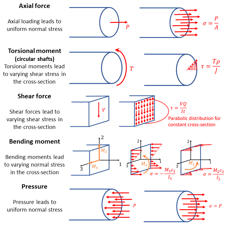
This image provides an excellent summary of the four primary load types we'll be combining. It shows the load, the resulting stress distribution, and the formula you'll use to calculate the stress.
Let's quickly review these:
-
Normal Stress () acts perpendicular to the surface.
- Axial Load (N or P): Creates a uniform stress across the cross-section.
- Bending Moment (M): Creates a stress that varies linearly from zero at the neutral axis to a maximum at the outermost fibers.
(where is the distance from the neutral axis)
- Axial Load (N or P): Creates a uniform stress across the cross-section.
-
Shear Stress () acts parallel to the surface.
- Torsional Moment (T): Creates a shear stress that varies linearly from zero at the center to a maximum at the outer surface of a shaft.
(where is the radial distance from the center) - Transverse Shear (V): Creates a shear stress that is typically highest at the neutral axis.
While important, this stress is often negligible at the locations where bending and torsional stresses are maximal (i.e., the outer surface). We'll focus on it when it's most relevant.
- Torsional Moment (T): Creates a shear stress that varies linearly from zero at the center to a maximum at the outer surface of a shaft.
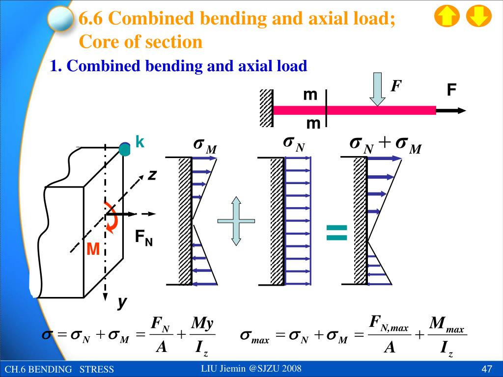
The key is that at any given point, normal stresses add together algebraically (tension is positive, compression is negative), and shear stresses add together vectorially.
2. A Systematic Process for Combined Loading Analysis
To handle these problems without getting lost, a structured approach is essential. Here is a reliable "recipe" for analyzing combined loading:
-
Perform Statics: "Cut" the component at the cross-section you want to analyze. Draw a free-body diagram of one side of the cut and use the equations of equilibrium (, etc.) to find all the internal forces and moments at the cut section. These are our fundamental loads:
- Normal Force,
- Shear Force,
- Bending Moment,
- Torsional Moment (Torque),
-
Calculate Section Properties: For the geometry of the cross-section, calculate the properties needed for the stress formulas:
- Area,
- Area Moment of Inertia,
- Polar Moment of Inertia,
-
Identify Critical Points: On your cross-section, determine the point(s) of interest. Often, we are interested in points where we expect stress to be highest. For example:
- Points on the top or bottom for maximum bending stress.
- Points on the outer surface for maximum torsional stress.
-
Calculate Individual Stresses: At your chosen point, use the formulas from Part 1 to calculate the stress contribution from each internal load. A key insight here is that a point's location determines which loads create stress. For instance, a point on the bending neutral axis will have zero normal stress from that bending moment.
-
Superimpose (Sum) the Stresses:
- Add all normal stresses () together to get the final (assuming the axis of the beam is 'x').
- Add all shear stresses () together to get the final .
This gives you the complete stress state (), which you can then use to draw a stress element and, as we learned last lesson, find the principal stresses.
3. A Worked Example: The Graphical Method
The best way to understand this process is to see it in action. The following video provides a detailed walkthrough of a combined loading problem. The instructor, Jeff Hanson, uses what he calls a "graphical method" which is an excellent way to build intuition. He considers each external force one-by-one and visualizes all the internal loads (bending, torsion, etc.) it creates on the cross-section.
Mechanics of Materials: Lesson 45 - Combined Loading, The Graphical Method
This video is a comprehensive example of analyzing a complex combined loading scenario. Pay close attention to the systematic way he breaks the problem down.
Please watch the video from the beginning. Here are the key segments to focus on: 0:00 - 4:30: Understand the problem setup and the 'menu' of possible stress formulas that can be used. 4:30 - 11:25: This is the core of the method. Observe how he analyzes each external force individually to determine what internal loads (axial force, shear, bending moment, torsion) it produces on the cross-section. His visualization is key. 11:25 - 22:48: Follow the calculations for the normal stress (\sigma) and shear stress ( au) at two different points, A and B. Notice how the location of the point (e.g., on a neutral axis) makes certain stress components zero. This directly applies the theory we've discussed. 22:48 - End: See how all the calculated components are assembled into final stress elements for points A and B, representing the complete stress state at each point.
This method of tracking the effect of each force is incredibly powerful. As an alternative, the method taught by Todd Fantz in the video Combined Loading Day 2 Example follows the "recipe" from Part 2 more formally: first find all internal loads, then calculate their stress contributions. Both methods lead to the same answer, so you can choose the one that feels more intuitive to you.
Test your understanding!
Imagine a solid circular shaft of radius is fixed into a wall. A simple arm of length is welded to the end of the shaft, perpendicular to it. A downward vertical force is applied to the very end of this arm.
Consider a point 'P' on the top surface of the shaft, right at the wall. What internal loads are present at the cross-section at the wall, and what types of stress does each one cause at point P?
Internal Loads to consider: Axial Force (N), Bending Moment (M), Torsional Moment (T), Transverse Shear (V).
Stress Types to consider: Axial (), Bending (), Torsional (), Transverse Shear ().
Show answer
Let's break it down using statics and the stress formulas. Let the shaft lie along the x-axis, the arm along the z-axis, and the force act in the negative y-direction.
-
Internal Loads at the Wall:
- Axial Force (N): There are no forces acting along the x-axis, so .
- Torsional Moment (T): The force acting at a distance from the shaft's centerline creates a torque about the x-axis. .
- Bending Moment (M): The problem is slightly ambiguous about the arm's orientation, let's assume the shaft is horizontal and the arm sticks out horizontally too. The force F is applied at some distance from the wall (the length of the shaft). Let's call the shaft length . Then the force creates a bending moment about the z-axis at the wall: .
- Transverse Shear (V): The force is transmitted along the shaft as a downward shear force. At the wall, .
-
Stresses at Point P (Top Surface at the Wall):
- Axial Stress (): Since , this is zero.
- Bending Stress (): The bending moment causes tension on the top of the shaft and compression on the bottom. Since P is on the top, it experiences maximum tensile stress from bending: .
- Torsional Shear Stress (): The torque creates shear stress. Since P is on the outer surface, it experiences maximum shear stress from torsion: .
- Transverse Shear Stress (): The shear force creates a parabolic stress distribution. For a circular cross-section, the shear stress is maximum at the neutral axis and zero at the top and bottom surfaces. Since P is at the top, .
Conclusion for Point P: It experiences a combination of normal stress from bending () and shear stress from torsion (). There is no stress from axial load or transverse shear at this specific point.
Conclusion
Today, we've connected the dots between external forces and the internal stress state of a component. You now have a systematic method to dissect any combined loading problem and determine the specific values of , , and at a point of interest.
Key Takeaways:
- The stress at a point in a component is the superposition of stresses from all internal loads acting at that cross-section (axial, bending, torsion, and shear).
- The analysis process is systematic: Statics to find internal loads Geometry for section properties Calculation of individual stresses at a point Summation to find the final stress state.
- The location of a point is critical. A point on a neutral axis for bending will have zero bending stress, and a point on the outer fiber of a round shaft will have zero transverse shear stress.
Next Lesson Preview:
We have now come full circle. You can:
- Take a loaded component and find the stress state () at a critical point (Today's lesson).
- Take that stress state and find the principal stresses () (Previous lesson).
What's next? We need to ask the ultimate engineering question: "Will it break?" In the next lesson, we will explore Failure Theories. We will learn how to take the principal stresses and compare them to the material's yield strength using criteria like the Maximum Shear Stress (Tresca) theory and the von Mises theory. This will allow us to calculate a factor of safety and make a definitive assessment of the design's integrity.
Can't find a good explanation? Sign up and we'll make it for you
Sign up