
Hello! Welcome to the next lesson in your study of stress analysis.
In the previous lesson, we learned how to use the stress transformation equations to find the normal () and shear () stresses on any plane rotated by an angle . This was a crucial step in understanding that stress is a directional quantity.
Today, we address the learning outcome: Calculate principal stresses and maximum in-plane shear stress using transformation equations or Mohr's circle. We'll focus on finding the specific orientations where the normal and shear stresses reach their maximum and minimum values. These values, particularly the principal stresses (max/min normal stresses) and the maximum in-plane shear stress, are fundamental to predicting when a material will yield or fracture. This is a critical concept in engineering design, especially in aerospace, where ensuring structural integrity under complex loading is paramount.
We will cover two powerful methods to find these critical stress values:
- Analytical Method: Using direct formulas derived from the transformation equations.
- Graphical Method: Using a visual tool called Mohr's Circle.
1. Defining Principal Stresses and Maximum Shear Stress
As we rotate a stress element, the normal and shear stresses on its faces change. At certain angles, the normal stresses will reach their maximum and minimum values. At these specific angles, the shear stress becomes zero.
- Principal Stresses (): The maximum and minimum normal stresses at a point. They occur on planes where the shear stress is zero. These are often denoted as (maximum) and (minimum).
- Maximum In-plane Shear Stress (): The absolute maximum shear stress at a point in the 2D plane. This occurs on planes that are 45° away from the principal planes.
The following video provides an excellent visual introduction to these concepts.
Understanding Stress Transformation and Mohr's Circle
This video from The Efficient Engineer explains why we are interested in finding maximum stress values and defines principal stresses.
Watch from the beginning to 3:40. Focus on the definitions of principal planes and principal stresses (\sigma_1 and \sigma_2) and the key fact that shear stress is zero on these planes.
2. The Analytical Method: Formulas for Principal Stresses
Since you prefer a formula-based approach, let's start there. The stress transformation equations from our last lesson can be used to derive direct formulas for the principal stresses and the maximum in-plane shear stress.
Stress transformations and Mohr’s circle
This document from Purdue University provides a clear derivation and summary of the key formulas. We'll focus on the final results.
Please read pages 7 through 9 of the document, which cover the section titled 'Principal normal stresses and maximum shear stress'. Focus on understanding and noting the final formulas for principal stresses (\sigma_{P1, P2}), the orientation angle ( heta_P), and the maximum in-plane shear stress ( au_{s1, s2}). Don't worry about memorizing the derivations.
Here is a summary of those essential formulas:
Principal Stresses:
The two principal stresses, and , are calculated using:
The + sign gives the maximum principal stress (), and the - sign gives the minimum principal stress ().
Maximum In-plane Shear Stress:
The maximum in-plane shear stress is equal to the square root term from the principal stress formula:
On the planes of maximum shear stress, the normal stress is not zero. It is equal to the average normal stress:
Orientation of Principal Planes:
The angle to the principal planes is found with:
This equation gives two angles for , 180° apart, which correspond to two principal planes 90° apart.
3. The Graphical Method: Mohr's Circle
While the equations are direct, the graphical method known as Mohr's Circle provides a more intuitive way to visualize stress transformation. It is a plot of the transformation equations, where every point on the circle represents the (, ) state on a specific plane.
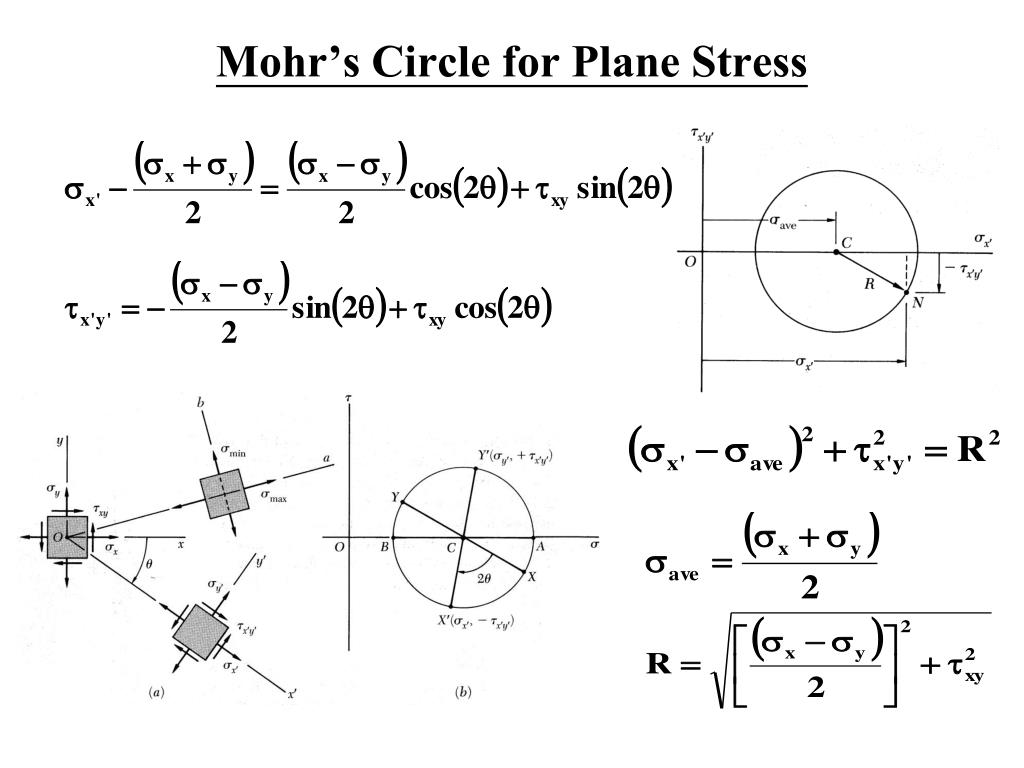
The next video gives a concise overview of how to construct the circle.
Understanding Stress Transformation and Mohr's Circle
Let's return to The Efficient Engineer video to see how Mohr's Circle is constructed and used to find the key stress values.
Watch from 3:40 to 6:03. Pay close attention to the sign conventions used, especially that positive shear stress is plotted downwards, and how angles on the circle relate to angles on the stress element (a 2 heta relationship).
4. A Complete Worked Example using Mohr's Circle
The best way to learn Mohr's Circle is to work through a problem from start to finish. The following video is a comprehensive tutorial that does just that.
Mechanics of Materials: Lesson 50 - Mohr’s Circle for Stress Transformation
In this video, Jeff Hanson provides a detailed, step-by-step guide to constructing and interpreting Mohr's circle for a given stress state. This practical demonstration will be very helpful.
This video is rich with detail. I recommend you watch the following segments carefully: 2:27 - 6:50: Learn how to get the coordinate points from the stress element and the crucial sign conventions. Note his 'clock is above, counter is below' mnemonic for shear stress. 6:50 - 12:24: Watch how to plot the points, find the circle's center (\sigma_{avg}), and calculate the radius (R = au_{max}). 12:24 - 15:28: See how to find the principal stresses (\sigma_1, \sigma_2) and maximum shear stress ( au_{max}) directly from the circle's geometry. 15:28 - 18:30: Understand how to calculate the angle to the principal planes ( heta_p) and the 2 heta relationship between the circle and the real-world element.
Key Steps for Constructing Mohr's Circle:
- Set up Axes: on the horizontal axis (positive to the right) and on the vertical axis (positive downwards).
- Identify Stresses: From the stress element, find , , and . Use the convention that a shear stress causing counter-clockwise rotation of the element is positive.
- Plot Points:
- Plot the "X-face" point at .
- Plot the "Y-face" point at .
- Draw the Circle: The line connecting these two points is the diameter. The point where this line crosses the -axis is the center of the circle. Draw the circle through points X and Y.
- Calculate Center and Radius:
- Center .
- Radius .
- Find Stresses:
- and .
- .
Test your understanding!
Let's use the same stress state from the previous lesson's exercise:
- MPa
- MPa
- MPa
Calculate the principal stresses () and the maximum in-plane shear stress (). You can use either the formulas or Mohr's Circle.
Show answer
Method 1: Using the Formulas
First, calculate the average stress and the radius term:
So, the maximum in-plane shear stress is 69.64 MPa.
Now, find the principal stresses:
The principal stresses are MPa (tension) and MPa (compression).
Method 2: Using Mohr's Circle
- Center: MPa.
- Coordinates:
- On the x-face, the shear of -25 MPa causes clockwise rotation (negative). However, the standard convention Jeff Hanson uses is to look at the arrow on the face. On the x-face, the arrow for is typically shown on the top or bottom face. Let's stick to the rotation convention: a shear stress is positive if it causes CCW rotation. In the standard diagram, MPa would cause a CW rotation. So the shear coordinate is negative.
- Wait, let's be careful with sign conventions. The standard equations use where a positive value is shown pointing up on the right face. A negative value points down. This causes CW rotation. So for the X-face point we plot .
- For the Y-face, we plot .
- Radius: The radius is the distance from the center (-15, 0) to either point, e.g., (50, 25).
- Horizontal distance: .
- Vertical distance: .
- MPa.
- Principal Stresses:
- MPa.
- MPa.
- Max Shear Stress: MPa.
Both methods yield the same results.
Conclusion
Today you've learned two methods for finding the most critical stress values in a 2D stress state: the principal stresses and the maximum in-plane shear stress. Mastering this is a significant step towards analyzing and predicting how components will behave under real-world loads.
Key Takeaways:
- Principal stresses () are the maximum and minimum normal stresses, occurring on planes with zero shear stress.
- The maximum in-plane shear stress () occurs on planes oriented 45° from the principal planes.
- You can find these values using either direct formulas or the graphical Mohr's Circle method.
- Mohr's circle provides a powerful visual tool for understanding the relationship between and as a function of orientation.
Next Lesson Preview:
So far, we have started with a given stress state (). But where do these stresses come from in a real object? In the next lesson, we will analyze states of combined loading. You will learn how to determine the stress state at a point in a component that is simultaneously subjected to axial forces, bending moments, and torsion. Once you determine that initial stress state, you can then apply the methods learned today to find the principal stresses and ultimate safety of the part.
Can't find a good explanation? Sign up and we'll make it for you
Sign up