Hello! Welcome back to our course on radioelectronics.
In the last lesson, we mastered the technique of simplifying resistor networks by calculating their equivalent resistance. We also noted that this method has its limits and won't work for all circuit topologies. Today, we'll learn a far more powerful and universal method for circuit analysis.
Introduction
Today's Topic: Kirchhoff's Current Law (KCL) for Nodal Analysis.
This lesson covers the fourth learning outcome in our "DC Circuit Fundamentals" module. We will introduce Kirchhoff's Current Law (KCL), one of the fundamental conservation laws in electronics, and then apply it in a systematic procedure called Nodal Analysis. This method allows us to solve for all the unknown voltages in virtually any DC circuit, no matter how complex.
Time to complete: Approximately 50 minutes.
Recap from Previous Lesson:
- We learned to calculate the equivalent resistance for resistors in series () and parallel ().
- We used a step-by-step "break-it-down" method to simplify combination circuits into a single resistor.
- We acknowledged that this method fails for circuits that cannot be reduced this way (like bridge circuits), necessitating a more fundamental approach.
1. Kirchhoff's Current Law (KCL)
At the heart of nodal analysis is Kirchhoff's Current Law. It's a statement about the conservation of charge.
KCL states that the algebraic sum of currents entering any node is zero.
A more intuitive way to put it is:
The sum of currents flowing into a node must equal the sum of currents flowing out of that node.
Think of it like plumbing: at any junction, the total amount of water flowing in must equal the total amount flowing out. There are no "leaks" or "sources" of charge at a node.
To see a clear review of this principle, please watch this short segment from a familiar instructor.
Watch from 02:09 to 03:47. The video explains the sign convention (currents entering are positive, currents leaving are negative) and how they sum to zero at a junction.
2. The Nodal Analysis Method
Nodal analysis is a structured procedure that uses KCL to find unknown voltages at different points in a circuit.
Key Concepts:
- Node: A point in a circuit where two or more components are connected. An entire wire with no components on it is considered a single node.
- Reference Node (Ground): We choose one node in the circuit as our reference point, defined to be at 0 Volts. All other node voltages are measured relative to this reference. A good engineering practice is to choose the node with the most connections, which often simplifies the math.
- Node Voltage: The voltage potential at a node with respect to the reference node. These are the main variables we will be solving for.
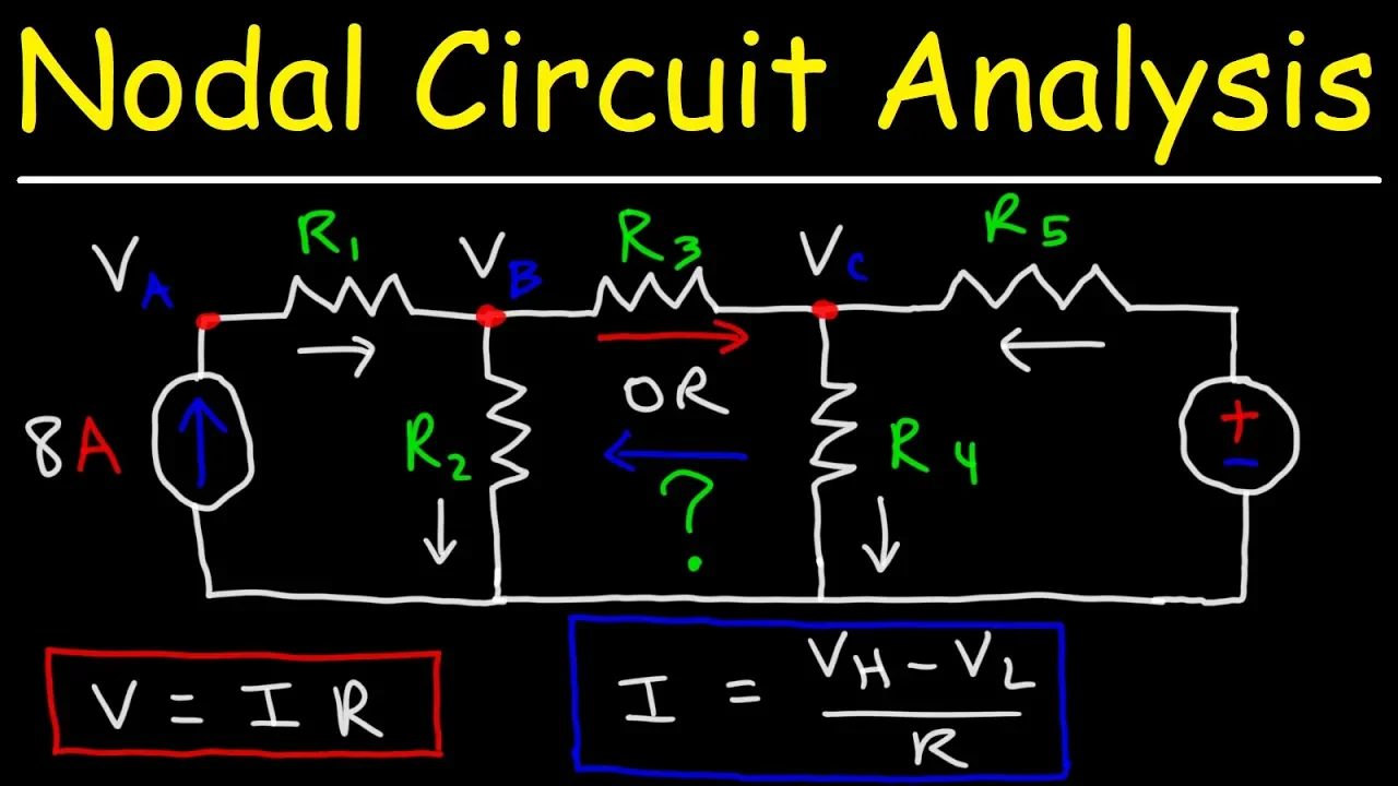
This video provides an excellent introduction to the core concepts of nodal analysis.

Please watch from the beginning until 01:50. Focus on how nodes are identified and why a reference node is chosen.
3. Combining KCL and Ohm's Law
The real power of nodal analysis comes when we combine KCL with Ohm's Law. We can express the unknown currents in our KCL equations in terms of the unknown node voltages.
Recall Ohm's Law: , which we can write as .
For a resistor connected between two nodes, say Node A and Node B, the voltage across the resistor is the difference in the node voltages, . Therefore, the current flowing from Node A to Node B is:
This equation is the workhorse of nodal analysis. It allows us to write KCL equations using only node voltages as our variables.
Watch the next part of the same video, which explains exactly how to apply this concept.
Watch from 01:50 to 03:26. This segment is crucial for understanding how to formulate the equations.
4. Nodal Analysis in Action: A Systematic Approach
Let's walk through the systematic steps of nodal analysis with some examples.
The General Procedure:
- Identify all nodes in the circuit.
- Select one node as the reference node (ground, 0V).
- Assign a variable (e.g., or ) to each of the other nodes. These are the node voltages you need to find.
- For each non-reference node, write a KCL equation.
- Use Ohm's Law () to rewrite the currents in your KCL equations in terms of the node voltages.
- Solve the resulting system of simultaneous linear equations for the unknown node voltages.
Example 1: A Single Unknown Node
Let's start with a simple circuit that only requires one KCL equation. This example clearly demonstrates steps 4-6.
Watch from 03:47 to 07:49. Observe how the instructor:
- Applies KCL at node
VA. - Expresses each current in terms of
VAand the known voltages/resistances. - Solves the resulting single-variable equation for
VA.
The KCL equation at Node A is: .
Written in terms of node voltages, this becomes:
Solving this equation gives you the node voltage .
Example 2: A System of Equations
Most circuits will have more than one unknown node voltage, which will require you to solve a system of equations. As an engineer with a strong math background, setting up and solving these systems will be a familiar process. The key is correctly applying the circuit laws to derive the equations.
This next video segment provides an excellent, detailed walkthrough of a circuit with two unknown nodes.
Watch from 03:26 to 11:01. Pay close attention to how two separate KCL equations are formulated, one for each unknown node, and then solved simultaneously.
- At Node 1 (VA):
- At Node 2 (VB):
The video then correctly substitutes the expressions for each current using Ohm's Law to arrive at a system of two linear equations, which can be solved for and .
5. Handling Voltage Sources in Nodal Analysis
What happens when a voltage source is present?
Case 1: Voltage Source Between a Node and Ground
This is the easy case. If a voltage source is connected directly between a non-reference node and the ground node, it simply sets the voltage at that node. For example, if a 12V source has its positive terminal at Node 2 and its negative terminal at ground, then . You have one fewer unknown to solve for!
The video segment from 15:26 to 18:17 in "The Complete Guide to Nodal Analysis" illustrates this scenario perfectly.
Case 2: Voltage Source Between Two Non-Reference Nodes (The "Supernode")
This is a more interesting case. A voltage source between two unknown nodes, say and , presents two issues:
- We don't know the current flowing through the voltage source.
- We can't write a standard KCL equation at either node.
We solve this using the supernode technique:
- We get one equation directly from the voltage source: .
- We form a "supernode" by drawing an imaginary boundary that encloses the voltage source and the two nodes it connects.
- We write a single KCL equation for this entire supernode, summing all currents entering or leaving the boundary.
This technique is a standard part of nodal analysis. To see it applied, watch the following segment.
Watch from 18:17 to 21:17. This clearly shows how to define the supernode and write the corresponding KCL equation.
Conclusion
Congratulations! You have just learned one of the most fundamental and powerful tools in circuit analysis. Nodal analysis provides a reliable, systematic way to solve for the voltages in any DC circuit.
Key Takeaways:
- Kirchhoff's Current Law (KCL): The sum of currents entering a node equals the sum of currents leaving it (conservation of charge).
- Nodal Analysis: A procedure to find unknown node voltages relative to a chosen reference node (ground).
- Core Technique: Write a KCL equation for each unknown node, expressing currents in terms of node voltages using Ohm's Law: .
- Systems of Equations: For circuits with N unknown nodes, you will solve a system of N linear equations.
- Supernodes: A special technique used to handle voltage sources connected between two non-reference nodes.
Preview of Next Lesson:
Now that we've mastered analyzing circuits from the perspective of node voltages (using KCL), we will learn a complementary technique called Mesh Analysis. This method focuses on finding unknown loop currents and is based on Kirchhoff's other fundamental law: Kirchhoff's Voltage Law (KVL).