Hello! Welcome to the next lesson in your journey through radioelectronics.
In the previous lessons, we focused on resistors, which are components that dissipate energy as heat. Now, we will introduce the other two fundamental passive components that behave quite differently.
Introduction
Today's Topic: Capacitors and Inductors: Principles of Energy Storage
This lesson covers the seventh learning outcome of our "DC Circuit Fundamentals" module. We will delve into the principles of capacitors and inductors, the two primary energy storage elements in electronics. You will learn how they work, the physical principles that govern them, the mathematical equations that define their behavior, and how they store energy—capacitors in electric fields and inductors in magnetic fields.
Understanding these components is absolutely essential, as their behavior is the foundation for everything from filtering and timing circuits to oscillators and antennas.
Time to complete: Approximately 60 minutes.
Recap from Previous Lesson:
- We explored the Voltage Divider Rule as a shortcut for analyzing series circuits.
- We highlighted the critical concept of loading, where connecting a device to a voltage divider affects its output voltage.
- We established that resistors are defined by a static relationship between voltage and current ().
Today, you will see that capacitors and inductors are defined by a dynamic, time-dependent relationship involving rates of change, which is a key concept you've encountered in your calculus review.
1. The Capacitor: Storing Energy in an Electric Field
A capacitor is a device designed to store energy in an electric field. Think of it as a tiny, rechargeable battery that can charge and discharge very quickly.
How a Capacitor Works
A capacitor, in its simplest form, consists of two conductive plates separated by an insulating material called a dielectric. When a voltage source (like a battery) is connected across the plates, it pushes charge carriers (electrons) onto one plate and pulls them from the other. This creates a separation of charge, with one plate becoming negatively charged and the other positively charged.
These separated charges create an electric field in the dielectric between the plates. This field holds the charges in place, storing potential energy.
The following video provides an excellent visual and conceptual introduction to what a capacitor is and how it charges.

Please watch from 02:06 to 04:50. Focus on:
- The physical structure: two conductive surfaces and a dielectric.
- The process of charging and how the electric field stores energy.
- The discharging process when a load is connected.
- The mention of different capacitor types (like electrolytic) and the importance of polarity.
To see a more detailed animation of the charging process and how the potential builds up, watch the first part of this next video.
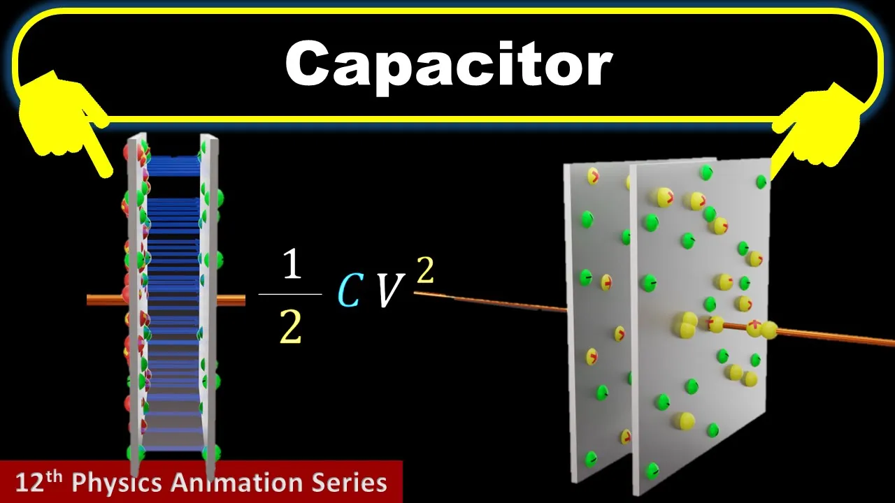
Watch from 00:20 to 02:34. This visualization will solidify your understanding of how the battery works to move charge onto the plates against the developing electric field.
Capacitance and its Governing Factors
The ability of a capacitor to store charge is called capacitance, denoted by the symbol . The unit of capacitance is the Farad (F), named after Michael Faraday. One Farad is a very large unit, so in practice, you will almost always see microfarads (, F), nanofarads (, F), and picofarads (, F).
The capacitance of a parallel-plate capacitor is determined by its physical construction:
- Plate Area (): Larger plates can hold more charge.
- Distance between plates (): A smaller distance results in a stronger electric field and higher capacitance.
- Dielectric Material (): The material's ability to support an electric field, its permittivity, affects capacitance.
This relationship is given by the formula:
where is the permittivity of the dielectric.
The ElectroBOOM video you watched earlier explains this relationship well. You can review it from 04:50 to 05:56 if you need a refresher.
The Constitutive Equation of a Capacitor
This is the most critical concept for circuit analysis. The amount of charge stored on a capacitor is directly proportional to the voltage across it:
As you know from your background, current () is the rate of flow of charge, . If we differentiate the charge equation with respect to time, we get the fundamental current-voltage relationship for a capacitor:
This equation tells us that the current through a capacitor is proportional to the rate of change of the voltage across it.
The following video segment does a fantastic job of explaining this equation and its consequences.
Watch from 07:29 to 10:02. The key takeaways are:
- The derivation of .
- A constant voltage () means zero current.
- A rapidly changing voltage means a large current.
This leads to a crucial rule: The voltage across a capacitor cannot change instantaneously. For the voltage to jump instantly, would have to be infinite, requiring an infinite current, which is physically impossible. This is analogous to state management in software: the state (voltage) cannot change without a process (current) acting on it over some non-zero time.
Energy Stored in a Capacitor
The work done to move charge onto the capacitor's plates against the electric field is stored as potential energy. We can derive the formula for this energy, .
The video below provides a clear, step-by-step derivation using integration, which will be a good refresher of your calculus skills.
Watch from 02:55 to 04:49. The derivation shows how integrating the power () over time leads to the energy formula.
The final result for the energy stored in a capacitor is:
Capacitor Behavior in DC Circuits
Based on the equation , when a capacitor is connected to a DC source, it charges up. As it charges, the voltage across it approaches the source voltage. Once the capacitor is fully charged, its voltage is constant, meaning . Consequently, the current flowing through it becomes zero.
Therefore, in a DC steady-state (after all changes have settled), a capacitor acts like an open circuit.
2. The Inductor: Storing Energy in a Magnetic Field
Just as a capacitor stores energy in an electric field, an inductor stores energy in a magnetic field. This property introduces a fascinating symmetry, or duality, between the two components.
How an Inductor Works
An inductor is typically a coil of wire, sometimes wrapped around a magnetic core (like iron).
- When current flows through the wire, it generates a magnetic field around the coil (Ampere's Law).
- If the current changes, the magnetic field it creates also changes.
- A changing magnetic field induces a voltage (or electromotive force, EMF) across the coil that opposes the original change in current (Faraday's Law of Induction and Lenz's Law).
This opposition to a change in current is the defining characteristic of an inductor. It gives the current an "inertia". You can think of an inductor as a heavy flywheel: it takes a sustained effort (a voltage) to get it spinning (current flow), and once it's spinning, it will resist any attempt to slow it down or speed it up.
Inductance and its Governing Factors
The ability of an inductor to oppose a change in current is called inductance, denoted by the symbol . The unit of inductance is the Henry (H).
Similar to capacitance, the inductance of a simple solenoid (a cylindrical coil) is determined by its physical construction:
where is the magnetic permeability of the core material, is the number of turns in the coil, is the cross-sectional area, and is the length of the coil.
The Constitutive Equation of an Inductor
The relationship between the voltage across an inductor and the current flowing through it is given by:
This equation states that the voltage across an inductor is proportional to the rate of change of the current through it.
Notice the beautiful duality with the capacitor's equation (). The roles of voltage and current are swapped.
This relationship leads to the inductor's primary rule: The current through an inductor cannot change instantaneously. For the current to jump instantly, would be infinite, requiring an infinite voltage, which is impossible. The inductor's "inertia" prevents this.
Energy Stored in an Inductor
The work done to push current through the coil against the opposing induced voltage is stored as energy in the magnetic field. We can derive this in a way that mirrors the capacitor energy derivation.
Power is . Substituting the inductor's voltage equation:
Energy is the integral of power.
So, the energy stored in an inductor is:
Inductor Behavior in DC Circuits
In a DC steady-state, the current is constant. This means . According to the inductor's equation (), the voltage across an ideal inductor becomes zero.
Therefore, in a DC steady-state, an inductor acts like a short circuit (a piece of wire). This is the dual of the capacitor's open-circuit behavior.
3. Summary: The Duality of Capacitors and Inductors
The symmetrical relationship between capacitors and inductors is a deep and powerful concept in electronics. Understanding this duality will help you remember their properties.
| Property | Capacitor (C) | Inductor (L) |
|---|---|---|
| Stores Energy In | Electric Field | Magnetic Field |
| Governing Equation | ||
| Fundamental Property | Voltage cannot change instantaneously. | Current cannot change instantaneously. |
| Energy Stored | ||
| Behavior in DC Steady-State | Acts as an Open Circuit (zero current) | Acts as a Short Circuit (zero voltage) |
Conclusion
You have now been introduced to the two fundamental energy-storage components in electronics. Unlike resistors that continuously dissipate energy, capacitors and inductors store it and can release it back into the circuit.
Key Takeaways:
- Capacitors store energy in an electric field. Their current depends on the rate of change of voltage (). Voltage across a capacitor cannot change instantly. In DC steady-state, they act as an open circuit.
- Inductors store energy in a magnetic field. Their voltage depends on the rate of change of current (). Current through an inductor cannot change instantly. In DC steady-state, they act as a short circuit.
- The relationship between these two components is described by the principle of duality, where the roles of voltage and current are interchanged.
Preview of Next Lesson:
Just as we learned to combine resistors in series and parallel, the next logical step is to do the same for our new components. In the next lesson, we will cover "Calculating Equivalent Capacitance and Inductance for Series/Parallel Combinations." You will find that the rules for combining them are also beautifully dual to one another.