Hello! Welcome back to your course on radioelectronics.
In our last lesson, we introduced the fundamental energy storage components: capacitors and inductors. We explored how they store energy and established the crucial concept of duality in their behavior. Now, let's learn how to handle circuits containing multiples of these components.
Introduction
Today's Topic: Calculating Equivalent Capacitance and Inductance for Series/Parallel Combinations
This lesson is the final one in our "DC Circuit Fundamentals" module. It covers the essential skill of simplifying circuits by combining multiple inductors or capacitors into a single equivalent component. This process is identical in principle to what you've already mastered with resistors and is a foundational technique for analyzing more complex circuits, from filters to oscillators.
Time to complete: Approximately 40 minutes.
Recap from Previous Lesson:
- Capacitors store energy in an electric field, and their current is defined by . Voltage cannot change instantly.
- Inductors store energy in a magnetic field, and their voltage is defined by . Current cannot change instantly.
- We highlighted the principle of duality, where the roles of voltage and current are swapped between these two components. This principle will be very apparent in today's lesson.
1. Equivalent Inductance
Let's begin with inductors. You'll be pleased to know that the rules for combining inductors are exactly the same as the rules for combining resistors.
The following short video segment clearly states these rules.

Please watch from 00:00 to 00:31 to get a quick overview of the rules for combining inductors in series and parallel.
Inductors in Series
When inductors are connected in series, the total inductance is simply the sum of the individual inductances.
Why is this so?
Recall Kirchhoff's Voltage Law (KVL) and the inductor's constitutive equation, . In a series circuit, the current is the same through all components, and the total voltage is the sum of the individual voltages.
Comparing this to the equation for a single equivalent inductor, , we can see directly that must be the sum of the individual inductances.
Inductors in Parallel
When inductors are connected in parallel, the reciprocal of the total inductance is the sum of the reciprocals of the individual inductances.
For the special case of two inductors in parallel, you can use the familiar "product over sum" formula:
Why is this so?
In a parallel circuit, the voltage is the same across all components, and the total current is the sum of the individual currents (KCL). From , we can say . Integrating this, we find that the current in each branch is proportional to . Thus, the total current follows this reciprocal relationship.
Example Calculation
Now, let's watch the rest of the video to see these rules applied to a mixed series-parallel circuit. The strategy is the same as with resistors: start simplifying from the part of the circuit furthest from the input terminals and redraw the circuit after each step.
Watch from 00:31 to 02:56. Pay attention to how the circuit is systematically reduced:
- Combine the three inductors in series on the outer branch.
- Redraw the circuit.
- Combine the two resulting parallel inductors.
- Redraw the circuit.
- Combine the final three inductors in series to find the total equivalent inductance.
2. Equivalent Capacitance
Now for capacitors. This is where the duality we discussed becomes very clear. The rules for combining capacitors are the opposite (or dual) of the rules for resistors and inductors.
Capacitors in Parallel
When capacitors are connected in parallel, the total capacitance is the sum of the individual capacitances.
This is like resistors in series.
Why is this so?
Physically, placing capacitors in parallel is like adding their plate areas together, which directly increases the total capacitance. Mathematically, in a parallel circuit, voltage is the same across all components, and the total current is the sum of the individual currents (KCL).
Comparing this to , we see that is simply the sum.
Capacitors in Series
When capacitors are connected in series, the reciprocal of the total capacitance is the sum of the reciprocals of the individual capacitances.
This is like resistors in parallel. For two capacitors in series, the "product over sum" formula also applies:
Why is this so?
Physically, placing capacitors in series is like increasing the total distance between the end plates, which decreases the overall capacitance. Mathematically, for a series circuit, the current is the same through all components, and the total voltage is the sum of the individual voltages (KVL). From , we can say . Integrating, we find the voltage on each capacitor is proportional to . The total voltage therefore follows the reciprocal sum.
Example Calculations
The following video provides a clear explanation of these rules and works through several examples of increasing complexity.
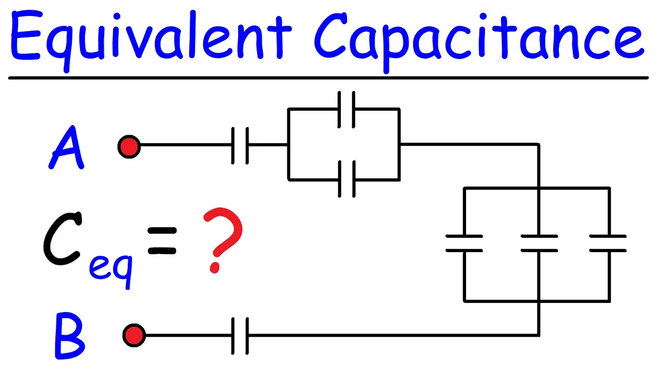
- First, watch from 00:01 to 02:53 to see the rules for parallel and series combinations explained with simple examples.
- Next, watch the segment from 04:04 to 06:13. This demonstrates the simplification strategy for a mixed circuit, similar to what we saw with inductors. Notice how the parallel section is combined first before tackling the series combination.
The video continues with even more complex examples, which you can watch if you'd like more practice, but these two segments cover the essential concepts and methods.
3. Summary Table: Duality in Combining Components
To make this perfectly clear, here is a summary of the rules for combining resistors, inductors, and capacitors. This table highlights the duality between L and C.
| Combination | Resistors (R) | Inductors (L) | Capacitors (C) |
|---|---|---|---|
| Series | |||
| Parallel |
As you can see, inductors behave just like resistors, while capacitors have the opposite rules. Keeping this pattern in mind is the easiest way to remember these formulas.
Conclusion
Congratulations on completing the first module on DC circuit fundamentals! You now have all the basic tools to analyze DC circuits containing resistors, capacitors, and inductors.
Key Takeaways from this Lesson:
- Inductors in series add directly (), and in parallel follow the reciprocal rule (), just like resistors.
- Capacitors in parallel add directly (), and in series follow the reciprocal rule (), which is the opposite of resistors.
- The strategy for simplifying mixed circuits is universal: identify series or parallel blocks, combine them, redraw the circuit, and repeat until you have a single equivalent component.
Preview of the Next Module:
So far, we've focused on DC circuits where voltages and currents are constant after an initial transient period. But the real power of radioelectronics lies in handling time-varying signals. Our next module, "AC Circuit Analysis," will dive into this. The very first lesson, "Introduction to Sinusoidal Signals," will lay the groundwork by introducing the mathematical language of AC signals: amplitude, frequency, and phase. This is where your study of radioelectronics truly begins.