Hello! Welcome back to our course on radioelectronics.
In our last lesson, you mastered Loop Analysis, a powerful method based on Kirchhoff's Voltage Law (KVL) for finding currents in any DC circuit. While that method is universally applicable, for simple series circuits, there's a much faster way to find the voltage across a component. This shortcut is one of the most frequently used tools in an electronics engineer's toolkit.
Introduction
Today's Topic: The Voltage Divider Rule and its Applications
This lesson covers the sixth learning outcome in our "DC Circuit Fundamentals" module. We will explore the Voltage Divider Rule, a simple but powerful formula for calculating how voltage is distributed among resistors in a series circuit. We will see how this rule is a direct consequence of KVL and Ohm's Law, and more importantly, we will examine its practical applications and critical limitations.
Time to complete: Approximately 50 minutes.
Recap from Previous Lesson:
- We established that Kirchhoff's Voltage Law (KVL) dictates that the sum of all voltage drops and rises around any closed loop must be zero.
- We applied KVL in the Loop Analysis procedure to set up and solve a system of equations for unknown loop currents.
Today, we'll build directly on those principles to derive a valuable shortcut.
1. What is a Voltage Divider?
At its core, a voltage divider is simply a series circuit of two or more resistors. Its purpose is to take a larger voltage and "divide" it down to a smaller, desired voltage. This is a fundamental task in electronics, from creating reference levels for sensors to biasing transistors.
To build your intuition, the following animated video provides a great conceptual overview. It visualizes voltage as energy and explains why both resistors are essential for the division to occur.
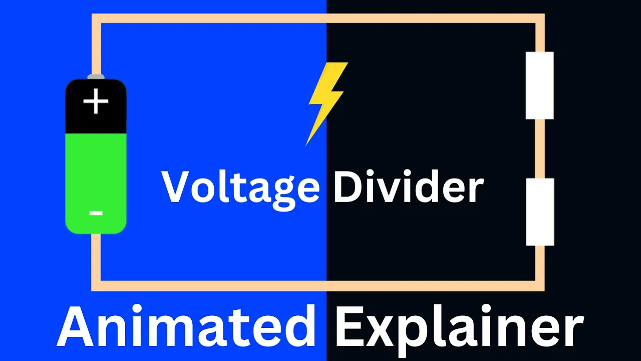
Please watch from the beginning to 02:58. Focus on:
- How voltage is "dropped" across each resistor in series.
- Why the second resistor, , is crucial for creating the divided voltage.
As you saw, the voltage is split proportionally across the resistors. This relationship is captured by a simple formula.
2. The Voltage Divider Rule and its Derivation
While you could always calculate the total current and then use Ohm's Law to find the voltage across a specific resistor (as we did in previous lessons), the Voltage Divider Rule lets you do it in one step.
For a simple series circuit with an input voltage and two resistors and , the output voltage across is given by the formula:
Notice the structure: the output voltage is a fraction of the input voltage. That fraction is the ratio of the resistor you're measuring across () to the total resistance of the chain ().
This next video segment demonstrates the utility of this formula by comparing the two-step Ohm's Law calculation with the one-step Voltage Divider Rule.
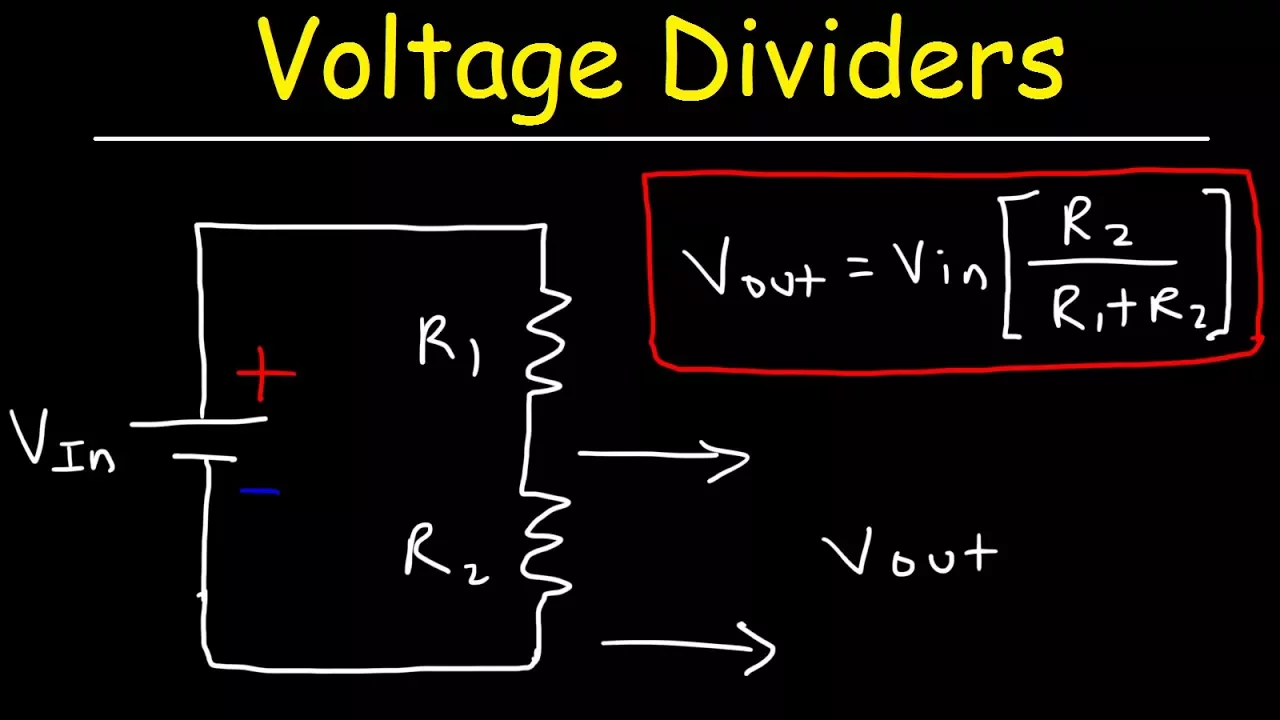
Watch from 00:00 to 02:15. It provides a clear, practical example of the rule in action.
Derivation from KVL and Ohm's Law
As an engineer, you know that formulas don't appear from nowhere. The Voltage Divider Rule is a direct consequence of the laws you've already learned.
-
Find the Total Current (KVL/Ohm's Law): For a simple series circuit, the total resistance is . From Ohm's law, the current flowing through the entire loop is:
-
Find the Output Voltage (Ohm's Law): The voltage across resistor is simply the current flowing through it multiplied by its resistance:
-
Substitute: Now, substitute the expression for from step 1 into step 2:
This simplifies to the Voltage Divider Rule. It's not a new law, but a convenient application of existing ones.
3. Application: Designing with the Voltage Divider
Beyond analyzing existing circuits, the rule is essential for design. For instance, if you have a 12V source but need a 3V reference, how do you choose the right resistors?
The following video walks through two excellent design examples. It shows how to calculate the required resistor values to achieve a specific output voltage and current draw.
Please watch from 02:15 to 07:47. This demonstrates the practical process of moving from requirements to a working circuit design.
4. The Critical Limitation: The Effect of a Load
So far, we've only considered an "unloaded" or "open-circuit" voltage divider. This is an idealization. In any real application, you will connect something to the output of your divider—this is called the load. The load might be a sensor, the input to an amplifier, or another part of a larger circuit.
Crucially, every load has its own internal resistance. When you connect this load, you are placing its resistance in parallel with .
This is where the simple formula can lead you astray if you're not careful.
First, let's get a qualitative understanding of the problem. This video segment explains why the load's resistance (or impedance) matters.
Watch from 04:28 to 05:57. The key takeaway is that an ideal load has very high resistance, so it "sips" a tiny amount of current and doesn't disturb the voltage.
Now, let's analyze this effect quantitatively. The following, more detailed video segment calculates the exact impact of a load on the output voltage. This is perhaps the most important part of the lesson for practical applications.
Watch from 07:47 to 16:54. Pay close attention to:
- How the equivalent resistance of and the load resistor () is calculated.
- How this new equivalent resistance replaces in the voltage divider formula.
- The demonstration of how a lower causes a larger drop in the output voltage.
- The rule of thumb: To ensure the output voltage doesn't change significantly, the load's resistance should be at least 10 times (and preferably 100 times) greater than the resistance of .
This "loading effect" is a bit like a software system design problem: a server (the voltage source) might have plenty of capacity, but a single, inefficient client (the low-resistance load) that makes too many requests can bog it down, causing latency for everyone. A well-behaved client (high-resistance load) makes minimal demands, allowing the system to operate as intended.
Conclusion
You've now learned about the Voltage Divider Rule, a fundamental shortcut in circuit analysis, and its crucial real-world limitations.
Key Takeaways:
- The Voltage Divider Rule is a formula to quickly calculate the voltage across a resistor in a series circuit: .
- It is derived directly from KVL and Ohm's Law.
- The Loading Effect: Connecting a load to the output places the load's resistance in parallel with the divider's bottom resistor, causing the output voltage to drop.
- Rule of Thumb: To minimize voltage drop, the load resistance should be significantly higher (at least 10x) than the resistance of the divider resistor it is in parallel with.
- Primary Application: Voltage dividers are excellent for creating reference voltages for high-impedance inputs (like amplifier or microcontroller inputs). They are generally inefficient and poorly regulated for powering low-impedance loads.
Preview of Next Lesson:
We have now covered the three fundamental passive components defined by their relationship between voltage and current: resistors (), and in the next lesson, we will introduce the final two: Capacitors and Inductors. We will explore how they behave differently from resistors by storing energy in electric and magnetic fields, respectively.