
Hello! Welcome to your fourth lesson on AC circuits.
In our last lesson, we used phasor diagrams as a graphical tool to analyze the phase relationships in series RLC circuits. We saw how the individual voltage phasors for the resistor, inductor, and capacitor combine to determine the overall phase angle between the source voltage and current. This led us to the "voltage triangle" and the formula .
While graphical methods are intuitive, they can be cumbersome for calculation. Today, we will achieve the learning outcome: Calculate impedance for series RLC circuits using phasors or complex numbers. We will formalize the phasor concept using complex numbers, a powerful mathematical tool that combines magnitude and phase into a single entity. Given your background and current studies in pure mathematics, this lesson will provide a direct and powerful application of complex number theory to a physical system.
From Graphical Phasors to Complex Numbers
Representing sinusoidal AC quantities as rotating vectors (phasors) is effective, but adding them graphically is imprecise. The complex plane provides a perfect algebraic framework for this. A complex number can represent a vector with a real component and an imaginary component . We can use this to represent our phasors.
In electrical engineering, the imaginary unit is denoted by instead of to avoid confusion with current, .
Let's start with a short video that introduces this idea and defines the central concept of this lesson: impedance.
Introduction to Phasors, Impedance, and AC Circuits
This video from Charles Clayton provides a concise introduction to why we use complex numbers in AC circuits and how they are used to define impedance.
Please watch from the beginning to 02:08. Focus on the motivation for replacing time-dependent sine waves with complex numbers (phasors) and the definition of impedance as a complex quantity with resistance (real part) and reactance (imaginary part).
As the video explained, we can represent a sinusoidal voltage by a complex number whose magnitude is the RMS value () and whose angle is the phase . The central idea is a generalization of Ohm's Law:
- In DC circuits:
- In AC circuits: , where , , and are all complex numbers.
Impedance () is the measure of the total opposition to current flow in an AC circuit. It's a complex quantity that accounts for both resistance and reactance.
where:
- is the resistance, the real part of impedance.
- is the reactance, the imaginary part of impedance.
The Complex Impedance of R, L, and C
The real power of this method comes from defining a unique complex impedance for each component. We can derive these by assuming a sinusoidal current and finding the resulting voltage across each component. Using Euler's formula, , we can represent the current as the real part of a complex exponential: . For simplicity in calculations, we work with the full complex forms and .
-
Resistor (R): The voltage is simply .
The impedance is . It's purely real, indicating no phase shift. -
Inductor (L): The voltage-current relationship is .
If , then .
Substituting this in gives .
The impedance is . This is purely imaginary and positive. The factor represents the +90° phase shift (voltage leads current). -
Capacitor (C): The relationship is , or .
Integrating gives .
So, .
The impedance is .
Since , we can write . This is purely imaginary and negative, with the factor representing the -90° phase shift (voltage lags current).
This derivation shows how the calculus of derivatives and integrals elegantly transforms into simple multiplication and division in the complex frequency domain.
The following document from a University of Illinois physics course formally derives these complex impedances. It provides a rigorous foundation for what we've just discussed.
Please read the sections titled 'complex number algebra', 'Impedances of capacitors and inductors', and 'Complex impedances'. Don't worry about the power series expansions; focus on how the exponential form e^{i\omega t} is used with the differential/integral relationships for L and C to derive their impedances, Z_L = i\omega L and Z_C = 1/(i\omega C). Note they use 'i' instead of 'j'.
Analyzing a Series RLC Circuit
One of the great advantages of complex impedance is that components in series are handled by simple addition, just like resistors in a DC circuit.
For an RLC circuit, the total impedance is:
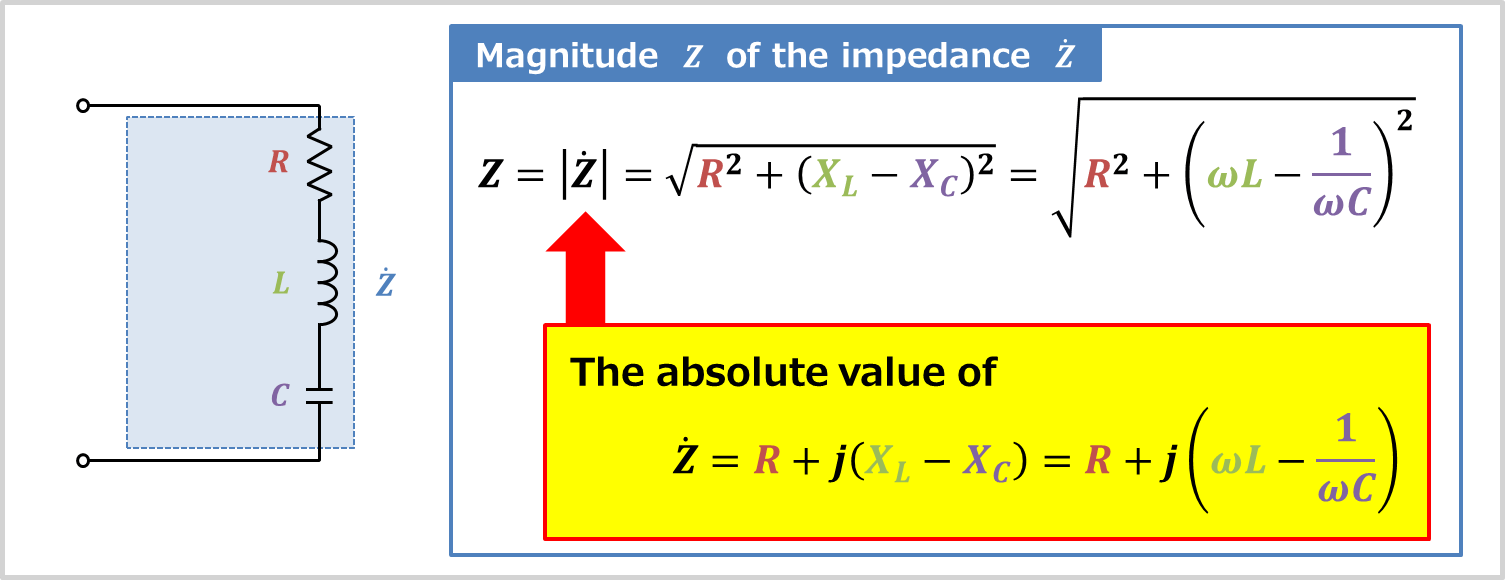
This is a central result. The total impedance is a complex number where:
- The real part is the resistance .
- The imaginary part is the total reactance .
Rectangular and Polar Forms
We can express in two ways:
- Rectangular Form:
- Polar Form:
Where:
- The magnitude is calculated using the Pythagorean theorem:
This magnitude gives the ratio of the RMS voltage to the RMS current: . - The phase angle is the argument of the complex number:
This is the same phase angle we found using the voltage triangle, but now it emerges directly from the algebra of complex numbers.
Worked Example
Let's apply this to a concrete problem. The following resource provides a clear, step-by-step example.
Current and Voltages Computations in Series RLC circuit
This page from Math for Engineers demonstrates how to use complex numbers to analyze a series RLC circuit. The worked example will solidify your understanding of the calculation process.
Please read and work through 'Example 1' in Section C. Follow the steps: a) calculating the individual complex impedances and summing them to find the total Z, and b) using Ohm's law in complex form to find the current. Pay close attention to the conversion between rectangular and polar forms.
Let's summarize the steps from that example:
- Given: A series RLC circuit with , , , and a source voltage with .
- Calculate Individual Impedances:
- Calculate Total Impedance (Rectangular Form):
- Convert to Polar Form:
- Magnitude:
- Phase Angle:
- So,
The final result tells us everything we need to know: the total opposition to current is , and the voltage will lead the current by (an inductive circuit).
Test your understanding!
Consider a series RLC circuit with , , and .
At what angular frequency will the total impedance be purely resistive (i.e., its imaginary part is zero)? What is the value of the impedance at this frequency?
Show answer
The total impedance is .
For the impedance to be purely resistive, the imaginary part must be zero:
This specific frequency is known as the resonant frequency. Plugging in the values:
At this frequency, the impedance is simply the resistance, since the reactances cancel out:
Conclusion
Today we have transitioned from a graphical understanding of AC circuits to a more powerful and efficient algebraic one using complex numbers.
Key Takeaways:
- Complex impedance () generalizes resistance to AC circuits, combining resistance (real part) and reactance (imaginary part) into a single complex number: .
- The impedances for individual components are:
- Resistor:
- Inductor:
- Capacitor:
- For a series RLC circuit, the total impedance is the simple sum: .
- The magnitude of the total impedance, , determines the ratio of voltage to current amplitudes ().
- The argument (angle) of the total impedance, , is the phase angle between the voltage and the current.
Preview of the Next Lesson:
Now that we have a solid grasp of impedance, we are ready to tackle the crucial topic of power in AC circuits. You've likely seen power ratings on appliances given in Watts (W), but in AC systems, you'll also encounter Volt-Amps (VA) and VAR. In our next lesson, we will explore real, reactive, and apparent power, and see how the impedance triangle we've implicitly worked with today has a direct analogue in the "power triangle". This will be essential for understanding power factor and efficiency in real-world systems.
Can't find a good explanation? Sign up and we'll make it for you
Sign up