Hello! In our previous lessons, we've focused on using diodes for power conversion, culminating in the design of the full-wave rectifier. We saw how diodes act as one-way gates for current to transform AC into pulsating DC. Now, we will pivot from power applications to signal processing.
Introduction
Approximate time to complete: 55 minutes
This lesson covers the learning outcome: Diode Application: Voltage Clipping and Clamping Circuits. We will explore how diodes, in combination with resistors and capacitors, can be used to precisely shape and manipulate AC waveforms.
Your background in radiophysics gives you a great foundation for this topic. These circuits are fundamental building blocks in communication systems and test equipment. We will cover two distinct but related applications:
- Clipping Circuits (Limiters): These circuits cut off or "clip" a portion of a waveform that exceeds a certain voltage, which is essential for protecting sensitive components from over-voltage and for general wave-shaping.
- Clamping Circuits (DC Restorers): These circuits shift an entire AC waveform vertically, adding a DC component to "clamp" its positive or negative peak to a specific voltage level. This is a critical function in areas like video signal processing.
By the end of this lesson, you will understand the operational principles and analysis techniques for both types of circuits.
1. Clipping Circuits: Limiting Signal Voltage
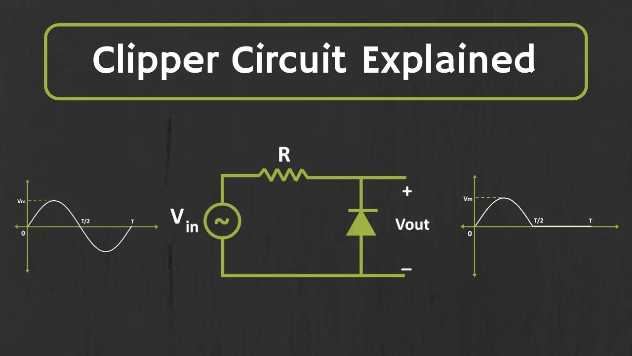
A clipper circuit uses one or more diodes to prevent a signal's output voltage from exceeding a predefined level. They are also commonly called limiters. The simplest form is a diode and a resistor, but by adding a DC bias voltage, we can set the clipping level to almost any value.
Let's begin by watching an excellent overview that builds from the simplest clipper to more complex biased configurations.
1.1. Basic Clipper Concepts
First, let's understand the fundamental principle and the two main configurations: series and parallel.
- Watch this segment: (0:12 - 3:35).
- What to focus on:
- The core function: clipping part of a waveform without distorting the rest.
- The difference between a series clipper (diode in series with the load) and a parallel clipper (diode in parallel with the load). We will focus primarily on the parallel configuration, as it is very common.
- The analysis of the simple positive and negative parallel clippers using an ideal diode. Notice how the diode acts like a closed switch when forward-biased, shorting the output to ground and thus "clipping" that part of the waveform.
- Time to watch: Approx. 3.5 minutes.
As you saw, a simple parallel clipper with an ideal diode clips the waveform at 0V. For a positive clipper, the diode conducts and shorts the output during the positive half-cycle. For a negative clipper, the diode is reversed and conducts during the negative half-cycle.
1.2. Biased Clippers: Setting Custom Clipping Levels
Clipping at 0V is useful, but often we need to limit a signal at a specific, non-zero voltage. This is achieved with a biased clipper, which adds a DC voltage source in series with the diode.
- Watch this segment: (3:35 - 7:12).
- What to focus on:
- Non-Ideal Diode Effect (3:35): The video first introduces the practical diode model. The clipping doesn't happen at 0V, but at the diode's forward voltage, (approx. 0.7V for silicon). So, a negative clipper will clip at -0.7V.
- Biasing (4:13): This is the key concept. Observe how adding a DC voltage source, , changes the turn-on condition for the diode. The diode now turns on not when the input voltage exceeds , but when exceeds .
- The new clipping level is . By selecting , you can set the clipping level precisely.
- Time to watch: Approx. 4 minutes.
1.3. Combination Clippers and an Alternative
We can combine two biased clippers to limit both the positive and negative peaks of a signal, creating a voltage "window."
- Watch this segment: (6:56 - 10:27).
- What to focus on:
- The circuit uses two parallel branches, each with a diode and a bias voltage, to set independent positive and negative clipping levels.
- Diode D1 and bias set the positive limit at .
- Diode D2 and bias set the negative limit at .
- The signal passes through undistorted as long as it stays between these two levels.
This segment also introduces a very important alternative: using two Zener diodes back-to-back. This is a compact and elegant way to achieve double-ended clipping, and it provides a perfect lead-in to our next lesson. A Zener diode is specifically designed to operate in reverse breakdown at a precise voltage.
2. Clamping Circuits: Shifting the DC Level
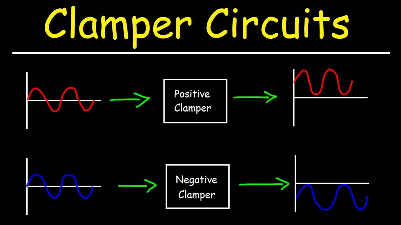
Unlike clippers that remove parts of a waveform, clampers shift the entire signal up or down by adding a DC component. This is also known as DC restoration. The shape and peak-to-peak amplitude of the waveform remain unchanged.
A clamper circuit consists of a capacitor, a diode, and a resistor. The capacitor is the key element that stores a DC charge, which then acts as the DC offset.
2.1. The Core Idea and Necessary Conditions
Let's understand the principle of operation and the critical design consideration for a clamper circuit to work correctly.
- Watch this segment: (0:00 - 6:06).
- What to focus on:
- The goal is to shift the signal's average voltage, not to change its shape.
- The circuit consists of an AC source, a capacitor, a diode, and a load resistor.
- The Time Constant Condition: This is a crucial point for an engineer. For the clamper to work, the capacitor must not lose significant charge when the diode is off. This means the discharge time constant () must be much larger than the charge time constant (). Since , we need the time constant to be much larger than the period of the input signal (). A rule of thumb is at least 10 times greater.
- Time to watch: Approx. 6 minutes.
2.2. Analyzing a Clamper Circuit
The analysis involves two steps: figuring out what happens during the first charging cycle and then determining the steady-state output.
- Watch this segment: (13:52 - 19:25).
(Note: This segment provides a very clear, step-by-step method. The earlier analysis in the video is a bit confusing, so we'll focus on this superior explanation.) - What to focus on: The video provides an excellent three-step process for drawing the output waveform of a negative clamper (one that shifts the signal down, clamping the positive peak).
Let's break down the logic:
- Identify the Charging Cycle: In the negative clamper shown, the diode points up. It will be forward-biased during the positive half-cycle of the input. During this time, the capacitor charges very quickly through the low resistance of the diode.
- Calculate the Capacitor Voltage (): The capacitor will charge until the voltage across it is just enough to make the diode turn off at the peak of the positive cycle. This happens when the voltage at the anode (from the capacitor) equals the voltage at the cathode (the diode drop, ). So, the capacitor charges to:
For the example in the video with and , . Because of the direction of current flow, the right plate of the capacitor becomes positive. - Determine the Output Waveform: Once charged, the capacitor acts like a DC voltage source of . The output voltage across the resistor is now the sum of the AC input and this DC offset from the capacitor. Because the capacitor is "pushing down" on the signal, the output is .
- Maximum Voltage: . The positive peak is "clamped" at the diode's forward voltage.
- Minimum Voltage: .
A positive clamper works analogously. The diode is flipped to point down. It charges during the negative half-cycle, and the capacitor develops a voltage that pushes the entire waveform up, clamping the negative peak at .
Conclusion
In this lesson, we explored two powerful signal-shaping techniques that leverage the non-linear behavior of diodes. Your radiophysics background will help you recognize these fundamental circuits in many larger systems.
Key Takeaways:
- Clippers (Limiters) use a diode's switching behavior to remove parts of a waveform above or below a certain voltage. By adding a bias voltage, this clipping level can be precisely controlled. They are essential for over-voltage protection and wave-shaping.
- Clampers (DC Restorers) use a capacitor-diode network to add a DC offset to an AC signal, shifting the entire waveform up or down without changing its shape. They are crucial for establishing a DC reference level for a signal, for example, after it has passed through AC-coupled amplifier stages.
- The key to a clamper's operation is a long RC time constant () relative to the signal's period, ensuring the capacitor holds its DC charge.
Preview of the Next Lesson:
We briefly mentioned that back-to-back Zener diodes provide a compact solution for double-ended clipping. In the next lesson, "Zener Diodes: Breakdown Mechanisms and Voltage Regulation," we will dive into the physics of Zener and avalanche breakdown, and see how these special-purpose diodes are used to create stable voltage references—a cornerstone of modern electronics.