Hello! In our last lesson, we saw how diodes can be used to clip and clamp AC waveforms, and we briefly mentioned that Zener diodes offer a compact way to perform double-ended clipping. Now, we'll explore these fascinating components in depth.
Introduction
Approximate time to complete: 60 minutes
This lesson covers the learning outcome: Zener Diodes: Breakdown Mechanisms and Voltage Regulation. While a standard diode is designed to block current in reverse bias, a Zener diode is specifically engineered to operate in its reverse breakdown region, maintaining a nearly constant voltage. This property makes it one of the most fundamental building blocks for creating stable voltage references.
Given your background in Radiophysics and Electronics, you'll appreciate that nearly every active circuit, from amplifiers to oscillators, relies on a stable DC bias voltage to function correctly. Zener diodes provide one of the simplest ways to achieve this.
We will cover:
- The unique V-I characteristics of a Zener diode.
- The underlying physics of breakdown: the Zener and Avalanche effects.
- The primary application of Zener diodes: designing a voltage regulator circuit.
- How to analyze and design a regulator to work under varying input voltage and load conditions.
Let's begin by understanding what makes a Zener diode different.
1. The Zener Diode's Unique Characteristic
A regular silicon diode conducts in the forward direction and blocks in the reverse direction. If the reverse voltage becomes too high, it enters an uncontrolled breakdown and is typically destroyed. A Zener diode looks similar, but it's designed to not only survive reverse breakdown but to operate there reliably.
The following video gives an excellent introduction to the Zener diode and its characteristic curve.

- Watch this segment: (0:00 - 3:50).
- What to focus on:
- The V-I curve of a Zener diode compared to a regular diode. Note how in the forward direction, it behaves identically.
- The key feature is the sharp, well-defined breakdown in the reverse-bias region at a specific voltage, known as the Zener Voltage ().
- The circuit symbol for the Zener diode, which cleverly mimics the shape of its V-I curve in the breakdown region.
- Time to watch: Approx. 4 minutes.
The key takeaway is that when reverse-biased beyond its Zener voltage, the diode will conduct and maintain a relatively constant voltage drop across it, regardless of the current flowing through it (within limits). This is the property we exploit for voltage regulation.
2. The Physics of Breakdown: Zener vs. Avalanche Effect
The term "Zener diode" is a bit of a catch-all. There are actually two distinct physical mechanisms that can cause this controlled reverse breakdown. Your Radiophysics background will make this distinction particularly interesting.
- Watch this segment: (3:33 - 7:59).
- What to focus on:
- The distinction between a regular diode's high, uncontrolled breakdown voltage and a Zener's manufactured, low, and stable breakdown voltage.
- Zener Effect: Occurs in heavily doped junctions at low voltages (typically < 5V). It's a quantum mechanical phenomenon where electrons "tunnel" through the narrow depletion region.
- Avalanche Breakdown: Occurs in more lightly doped junctions at higher voltages (typically > 6V). Here, high-energy electrons collide with atoms, creating more electron-hole pairs in a cascading "avalanche."
- In the ~5-6V range, both effects can be present.
- Time to watch: Approx. 4.5 minutes.
Though the underlying physics differs, any diode designed for reverse breakdown operation is commercially referred to as a Zener diode.
3. Zener Diodes for Voltage Regulation
The most common application for a Zener diode is to create a simple voltage regulator. The goal is to produce a stable output voltage from a higher, possibly fluctuating, input voltage source.
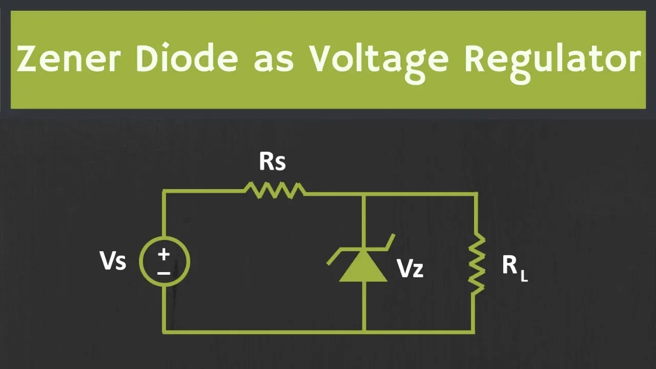
A basic Zener regulator consists of a series resistor () to limit the current and a Zener diode in parallel with the load ().
3.1. The Basic Principle and Ideal Model
First, let's establish the operating principle. When the input voltage is high enough to reverse-bias the Zener into breakdown, the voltage across it (and thus across the parallel load) is "clamped" at .
- Watch this segment: (2:40 - 5:38).
- What to focus on:
- The need for a series current-limiting resistor () to prevent excessive current from destroying the diode.
- The definition of the operating range for the Zener current, : it must be between a minimum value to stay in breakdown () and a maximum value set by the diode's power rating ().
- The ideal model: For initial analysis, we can replace the Zener diode with a constant DC voltage source of value once it's in breakdown.
- Time to watch: Approx. 3 minutes.
3.2. Analyzing the Regulator Circuit
Let's walk through the calculations for a regulator with a fixed input voltage and a fixed load. The video provides a clear, step-by-step example.
- Watch this segment: (5:38 - 11:12).
- What to focus on: The analytical process.
- Check if the Zener is ON: First, determine if the voltage across the Zener (without it in the circuit) is greater than . This is done by finding the Thevenin voltage across the load terminals, which is calculated using the voltage divider rule:
If , the Zener is in breakdown. - Calculate Currents: If the Zener is on, the output voltage is . We can now find the currents:
- Load Current:
- Source Current (through ):
- Zener Current (by KCL):
- Calculate Power Dissipation: Ensure the Zener can handle the power:
This value must be less than the diode's maximum power rating.
- Check if the Zener is ON: First, determine if the voltage across the Zener (without it in the circuit) is greater than . This is done by finding the Thevenin voltage across the load terminals, which is calculated using the voltage divider rule:
- Time to watch: Approx. 5.5 minutes.
3.3. Designing for Variable Conditions
In the real world, a regulator must maintain a constant output even when the load current or the input voltage changes. This is known as load regulation and line regulation, respectively. The following segments show how to determine the range of values for which the regulator will still function correctly.
-
Watch:
(11:12 - 17:34).- This shows how to find the minimum and maximum load resistance () that will keep the Zener operating within its valid current range ().
-
Watch:
(17:16 - 23:11).- This shows how to find the minimum and maximum supply voltage () that keeps the regulator functioning correctly.
These systematic analyses are crucial for robust engineering design. The core idea is to solve for the boundary conditions:
- The point where the Zener is about to turn OFF (current drops to ).
- The point where the Zener is about to be overloaded (current rises to ).
- Time to watch: Approx. 12 minutes total for both segments.
4. Practical Considerations and Limitations
Our analysis so far has used an ideal model. For practical design, we must account for non-ideal behaviors.
- Watch this segment: (7:45 - 10:19).
- What to focus on:
- Dynamic Resistance (): The reverse breakdown V-I curve is not perfectly vertical. It has a slope, which corresponds to a small internal resistance, often called dynamic impedance ().
- Impact on Regulation: Because of , the Zener voltage is not perfectly constant. It will change slightly as the Zener current () changes. The change in voltage is . This is why a simple Zener regulator's output voltage will still vary slightly with changes in line voltage or load.
- Time to watch: Approx. 2.5 minutes.
The EEVblog video demonstrates this effect clearly (13:08 - 16:40), showing how the output voltage creeps up as the input voltage (and thus Zener current) increases.
Finally, remember that a Zener diode needs a minimum amount of current to operate in its breakdown region.
- Watch this segment: (31:17 - 31:44).
- This short demo shows that below a certain threshold current (in the microamp range), the diode fails to regulate at its specified voltage.
- Time to watch: Approx. 30 seconds.
Conclusion
In this lesson, we demystified the Zener diode, a component that cleverly exploits a failure mode of regular diodes for a highly useful purpose.
Key Takeaways:
- A Zener diode is engineered to operate in its reverse breakdown region, providing a stable reference voltage ().
- The breakdown is caused by the Zener effect (quantum tunneling at <5V) or Avalanche breakdown (impact ionization at >6V).
- In a voltage regulator circuit, a series resistor () limits the current, and the Zener diode clamps the output voltage at .
- Designing a regulator involves calculating and ensuring the Zener current and power dissipation stay within safe operating limits, even as input voltage and load vary.
- Practical Zeners have a dynamic resistance (), which causes the output voltage to vary slightly with current, limiting the regulation performance.
Preview of the Next Lesson:
Now that we understand how to create stable DC voltages using Zener diodes, we are equipped to power active components. In our next lesson, "Bipolar Junction Transistor (BJT) Structure and Operating Principles," we will explore the first of these: a three-terminal device that can amplify signals and act as an electronic switch. The stable DC biasing we learned about today is essential for making transistors work as amplifiers.