Hello! Let's dive into the next lesson.
In our previous session, we developed a qualitative understanding of how a diode behaves under forward and reverse bias. We saw the I-V curve's distinct shape—exponential growth in one direction, near-zero current in the other. Today, we will give that curve a precise mathematical identity.
Introduction
Approximate time to complete: 45 minutes
This lesson covers the learning outcome: The Diode Equation: Modeling the I-V Relationship. We will introduce the Shockley diode equation, the fundamental formula that quantitatively describes the current-voltage characteristic you observed qualitatively in the last lesson.
Your background in radiophysics and calculus will be particularly helpful here, as we connect the physical behavior of the diode to a concise mathematical model. By the end of this lesson, you will be able to:
- Write and understand the Shockley diode equation and its components.
- Define thermal voltage (), ideality factor (), and reverse saturation current ().
- Calculate the thermal voltage at a given temperature.
- Use the diode equation to explain the diode's exponential forward current and constant reverse current.
This lesson bridges the gap between physical theory and practical circuit analysis, equipping you with the primary tool for calculating diode behavior.
1. Modeling Components: From Linear to Non-Linear
In circuit analysis, our goal is often to find a mathematical relationship between the voltage across a component and the current through it. For a simple resistor, this relationship is beautifully linear, described by Ohm's Law: . The I-V curve is a straight line.
As we saw in the last lesson, a diode is fundamentally different. Its I-V curve is highly non-linear. Therefore, it requires a more sophisticated model.
To set the stage, let's watch a short segment that contrasts the linear model of a resistor with the need for a non-linear model for a diode.
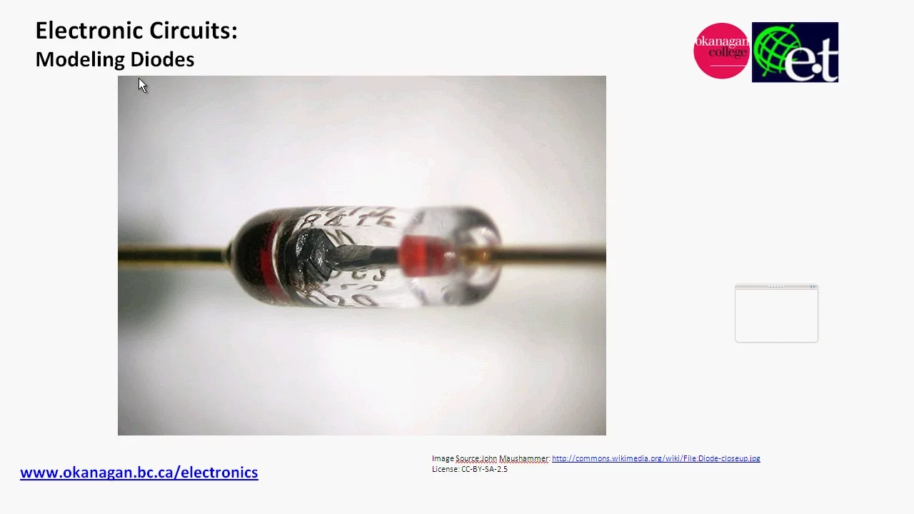
- What to focus on: The distinction between the linear I-V plot for a resistor and the complex, non-linear curve for a diode. This highlights why a simple equation like Ohm's Law is insufficient.
- Time: 02:50 - 06:16
This non-linear behavior is precisely what the Shockley diode equation captures.
2. The Shockley Diode Equation
The relationship between the diode current and the voltage across the diode is described by the Shockley diode equation:
This elegant equation models the entire I-V curve we discussed previously. To understand it, we must break down its components.
The following video provides a clear and direct explanation of the equation and each of its variables.
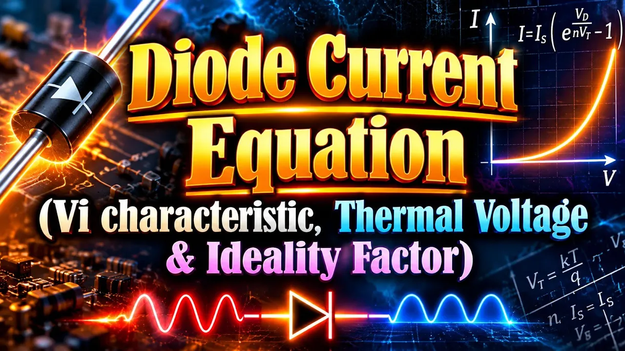
- What to focus on: Pay close attention as the video introduces each term in the equation. We will dissect them one by one.
- Time: 00:00 - 02:11
Let's summarize and expand on those key variables:
- : The total current flowing through the diode.
- : The external voltage applied across the diode terminals (positive for forward bias, negative for reverse bias).
- : The reverse saturation current. This is the small leakage current that flows during reverse bias, caused by minority carriers. As you recall from our last lesson, it is highly dependent on temperature but nearly independent of the reverse voltage. For silicon diodes, it's typically in the range of nanoamperes (nA).
- (eta): The ideality factor. This is an empirical parameter that accounts for how closely a real diode matches the "ideal" model.
- For Germanium (Ge) diodes, .
- For Silicon (Si) diodes, . This is due to more significant charge carrier recombination within the depletion region of silicon devices.
- : The thermal voltage. This crucial term links the diode's electrical behavior to temperature and fundamental physical constants.
3. The Thermal Voltage,
The thermal voltage, , represents the average thermal energy per unit charge. Its value is determined by the fundamental physics of the semiconductor junction.
Where:
- is the Boltzmann constant ().
- is the absolute temperature in Kelvin (K).
- is the elementary charge of an electron ().
The thermal voltage directly influences the shape of the I-V curve. As temperature increases, increases, which affects the steepness of the exponential current rise.
A very useful rule of thumb is the value of at room temperature. Let's see how that is calculated.
- What to focus on: How the values for k, T (300 K), and q are substituted to arrive at a standard value for .
- Time: 02:11 - 03:50
At a typical room temperature of (about 27°C), the thermal voltage is approximately:
This value is a cornerstone of semiconductor analysis and is frequently used as a default in calculations.
4. Analyzing the Equation's Behavior
Now, let's use the diode equation to mathematically confirm the diode's behavior in its different operating regions.
Case 1: Forward Bias ()
When the diode is forward-biased, is positive. For a silicon diode to be "on," is typically around 0.7 V. This is much larger than (e.g., ).
The exponent becomes a large positive number. Consequently, the term becomes huge, making the - 1 in the equation negligible.
Therefore, for forward bias, the equation simplifies to:
This confirms the exponential relationship between current and voltage that we observed in the I-V curve. A small increase in results in a large, exponential increase in .
Case 2: Reverse Bias ()
When the diode is reverse-biased, is negative. The exponent becomes a negative number.
If the magnitude of the reverse voltage is much greater than (e.g., ), the exponential term approaches zero.
The following part of the video walks through this exact derivation.
- What to focus on: Observe how setting to a negative value makes the exponential term tend to zero, leading to the final simplified result.
- Time: 04:29 - 08:33
As shown in the video, the equation simplifies to:
This mathematically proves that under reverse bias, the diode current is a small, constant negative value equal to the reverse saturation current , regardless of the specific reverse voltage (up until breakdown). This perfectly matches the flat region of the I-V curve we saw in the previous lesson.
Case 3: Zero Bias ()
If we apply no voltage, . The equation becomes:
This confirms that at thermal equilibrium, with no external voltage, there is no net current flow, just as we established two lessons ago.
Conclusion
Today, we've put a powerful mathematical formula to the physical behavior of the diode. This equation is the foundation for analyzing and designing circuits containing diodes.
Let's recap the key points:
- The Shockley diode equation, , provides a highly accurate model of the diode's I-V characteristics.
- The equation includes physical constants and parameters: the reverse saturation current (), the ideality factor (), and the thermal voltage ().
- At room temperature (300 K), the thermal voltage is approximately 26 mV.
- The equation successfully simplifies to describe the diode's behavior in its key operating regions: exponential current growth in forward bias and a constant leakage current () in reverse bias.
Preview of the Next Lesson:
With a solid physical and mathematical model in hand, we are now ready to put the diode to work. In the next lesson, Diode Application: The Half-Wave Rectifier, we will build our first practical diode circuit and see how its one-way conducting nature is used to convert AC voltage into DC voltage.