Hello! Welcome to the final lesson of our module on Analog Communication Systems.
In our previous lessons, we explored how signals are modulated, radiated by antennas like the half-wave dipole, and characterized by parameters like gain and impedance. We've successfully launched an electromagnetic wave into the world. But what happens next? How does that wave travel from the transmitter to a receiver that might be a few kilometers or even thousands of kilometers away?
This lesson addresses that very question. We will explore the primary modes of electromagnetic wave propagation. You will learn how the Earth's surface and atmosphere dictate the path a radio wave takes, and how this behavior is fundamentally dependent on the wave's frequency.
Learning Outcome:
By the end of this lesson, you will be able to describe the three main electromagnetic wave propagation modes: Ground wave, Sky wave, and Line-of-Sight, and understand their characteristics and applications.
1. An Overview of Propagation Paths
When a radio wave leaves a transmitting antenna, it can take several paths to reach a receiver. The three principal modes are illustrated below.
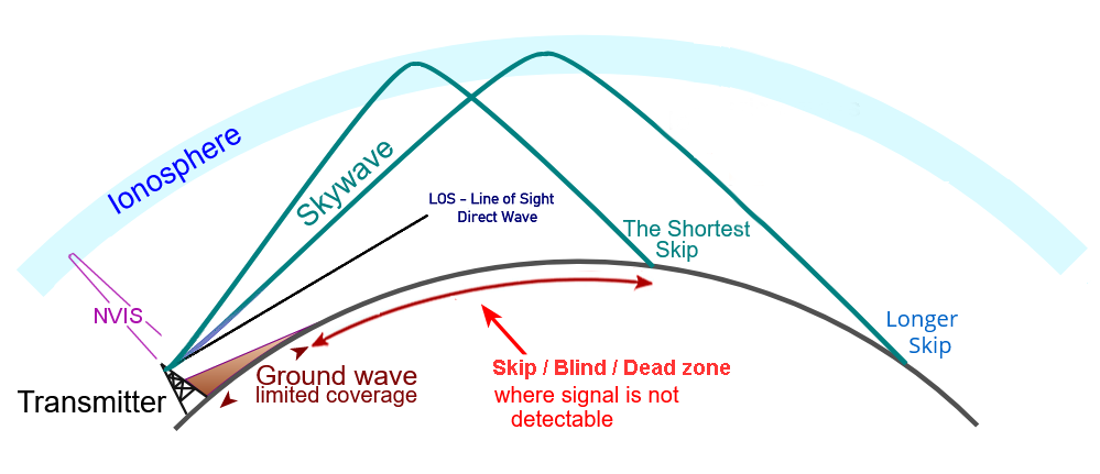
- Ground Wave: Travels along the surface of the Earth, following its curvature.
- Sky Wave: Travels up to the ionosphere, where it is refracted back down to Earth, enabling long-distance communication.
- Line-of-Sight (LOS) Wave: Travels in a straight line directly from the transmitting antenna to the receiving antenna. This is often called the Space Wave, which includes both the direct wave and any waves reflected off the ground.
To get a comprehensive overview of these phenomena, let's start with a document that introduces them all.
overview of electromagnetic wave propagation - Faculty
This document from the Naval Postgraduate School, 'Overview of Electromagnetic Wave Propagation', provides an excellent visual and conceptual introduction to the various ways radio waves travel.
Please read the first four pages. Start with the diagram on page 2, which visualizes the different paths. Then, read the 'Survey of Propagation Mechanisms' on pages 2-4. Focus on understanding the basic geometry of the direct path (LOS), ground wave, and ionospheric hop (sky wave).
Now, let's examine each of these modes in greater detail.
2. The Ground Wave
The ground wave is a wave that propagates along the surface of the Earth. It is able to follow the Earth's curvature due to a phenomenon called diffraction. As the wave travels, it induces currents in the ground, causing it to lose energy (attenuate). The effectiveness of ground wave propagation is highly dependent on three factors: frequency, polarization, and ground conductivity.
For a detailed exploration of these factors, the following resource is excellent.
Principles of Radio Wave Propagation
This chapter, 'Principles of Ground Wave Propagation', from a U.S. Army subcourse, offers a clear and structured explanation of this mode.
Please read the section titled 'PRINCIPLES OF GROUND WAVE PROPAGATION' (pages 2-1 to 2-7). Pay close attention to: The distinction between the surface wave and the space wave (we will treat the space wave as our Line-of-Sight mode). Why vertical polarization is superior for surface waves (Section 3.a.(2)). The effect of surface conductivity (Table 2-1). How frequency impacts attenuation (Section 3.a.(6)).
Key Characteristics of Ground Wave Propagation:
- Frequency: Ground wave propagation is most effective at low frequencies (VLF, LF, and MF bands). Attenuation increases dramatically with frequency, making it impractical above ~2 MHz.
- Polarization: Vertically polarized waves are essential. A horizontally polarized wave's electric field is parallel to the ground and is effectively short-circuited, causing rapid attenuation.
- Conductivity: The wave travels best over surfaces with high conductivity, like seawater. It performs poorly over dry, sandy, or heavily forested terrain.
- Applications: AM radio broadcasting (especially during the day), long-range navigation systems (Loran-C), and time signal stations (like WWVB).
3. The Sky Wave
For long-distance communication in the HF band (roughly 2-30 MHz), the sky wave is the dominant mode. This mode relies on the ionosphere, a region of the upper atmosphere (from ~50 to 400 km altitude) that contains electrically charged ions and free electrons created by solar radiation.
The ionosphere acts like a natural, variable mirror for radio waves, refracting them back towards the Earth.
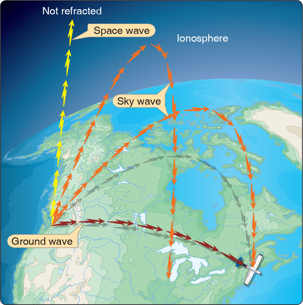
Let's dive into the mechanics of sky wave propagation.
Principles of Radio Wave Propagation
Continuing with the same U.S. Army document, the next chapter, 'Principles of Sky Wave Propagation', details the role of the ionosphere.
Please read the section 'PRINCIPALS OF SKY WAVE PROPAGATION' (pages 3-1 to 3-7). Focus on: The formation of the D, E, and F layers of the ionosphere and the processes of ionization and recombination. The concept of critical frequency and how it relates to whether a wave is refracted or passes into space. The formation of the skip distance and skip zone (Figure 3-6 is very helpful). The significant difference in propagation between day and night, particularly the role of the D layer.
Key Characteristics of Sky Wave Propagation:
- Ionospheric Layers: The ionosphere is stratified into layers (D, E, F1, F2). The D layer is lowest and absorbs MF/HF waves, but it largely disappears at night. The F layers are the highest and are primarily responsible for refracting HF waves for long-distance paths.
- Day/Night Cycle: This is the most critical factor. During the day, the D layer absorbs much of the HF energy, limiting range. At night, the D layer vanishes, and the F1 and F2 layers combine into a single, higher F layer, allowing for stable, long-distance (even global) communication. This is why you can hear distant AM stations at night—their signals, normally confined to a ground wave path, begin propagating via sky wave.
- Frequency: For a given path, there is a Maximum Usable Frequency (MUF) and a Lowest Usable Frequency (LUF) that define a usable "window" for communication.
- Applications: "Shortwave" international broadcasting, amateur (ham) radio, and over-the-horizon military and diplomatic communications.
4. The Line-of-Sight (Space) Wave
At frequencies above the HF band (VHF, UHF, and higher), the ionosphere becomes transparent. Radio waves pass right through it, making sky wave propagation impossible. At these frequencies, communication is limited to the Line-of-Sight (LOS) path.
The LOS wave is more accurately called the space wave, which consists of two components:
- The Direct Wave: Travels in a straight line from the transmitter to the receiver.
- The Ground-Reflected Wave: Reaches the receiver after reflecting off the Earth's surface.
These two components can add constructively or destructively at the receiver, leading to a phenomenon known as multipath fading. The range of LOS communication is limited by the curvature of the Earth and obstructions like hills and buildings. Due to slight bending (refraction) in the troposphere, the radio horizon is about 15% farther than the visual horizon.
Key Characteristics of Line-of-Sight Propagation:
- Frequency: This is the only mode available for VHF, UHF, and microwave frequencies.
- Range: Limited by the radio horizon. To increase range, antenna height is critical (e.g., placing antennas on tall towers or mountains).
- Applications: FM radio, television broadcasting, Wi-Fi, cellular communication, satellite links, and microwave point-to-point relays.
5. Summary: Frequency Determines the Mode
The most important takeaway is that the dominant propagation mode is determined by the signal's frequency. The following resource provides a concise summary linking frequency bands to their primary propagation mechanisms and applications.
overview of electromagnetic wave propagation - Faculty
Let's return to the Naval Postgraduate School document to tie everything together. This section neatly summarizes which modes are used at which frequencies.
Please read the sections 'Propagation Mechanisms by Frequency Bands' (page 7) and 'Applications of Propagation Phenomena' (page 8). This will solidify the connection between frequency, propagation mode, and real-world use.
Here is a summary table based on that information:
| Frequency Band | Primary Mode(s) | Typical Applications |
|---|---|---|
| LF/MF (30 kHz - 3 MHz) | Ground Wave (day), Sky Wave (night) | AM Radio, Navigation (Loran-C) |
| HF (3 - 30 MHz) | Sky Wave | Shortwave Broadcast, Amateur Radio, OTH Comms |
| VHF/UHF (30 MHz - 3 GHz) | Line-of-Sight (Space Wave) | FM Radio, TV, Cell Phones, GPS, Wi-Fi |
| SHF/EHF (> 3 GHz) | Line-of-Sight (Space Wave) | Satellite Comms, Microwave Links, Radar |
Conclusion
This lesson concludes our journey through the fundamentals of analog communication systems. We have seen how information is impressed upon a carrier wave (modulation), launched into space by an antenna, and how it finally travels to its destination via ground waves, sky waves, or line-of-sight paths.
Key Takeaways:
- Radio waves propagate through three main modes: Ground Wave, Sky Wave, and Line-of-Sight (Space Wave).
- The dominant mode is determined by the signal's frequency.
- Ground waves follow the Earth's surface and are effective at low frequencies (LF/MF), requiring vertical polarization.
- Sky waves use the ionosphere for long-distance refraction and are the primary mode for the HF band, with significant variations between day and night.
- Line-of-Sight propagation is a straight-line path used for VHF and higher frequencies, where range is limited by the radio horizon.
This module has laid a critical foundation. Understanding how signals are generated, transmitted, and propagated is essential before we can delve into the components that perform these tasks. In the upcoming modules, we will shift our focus from systems to circuits, starting with the physics of semiconductors and the operation of diodes, which are the building blocks of modern electronics.